Gas water heater and waste heat recycle method
A technology of gas water heater and waste heat recovery device, applied in indirect heat exchangers, fluid heaters, lighting and heating equipment, etc., can solve problems such as waste of heat, waste of resources, environmental pollution, etc., to improve thermal efficiency, reduce waste heat, protect environmental effects
- Summary
- Abstract
- Description
- Claims
- Application Information
AI Technical Summary
Problems solved by technology
Method used
Image
Examples
Embodiment 1
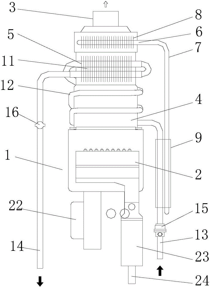
[0032] Such as figure 1 As shown, the gas water heater 1 described includes a combustion chamber 2, a smoke exhaust pipe 3, a heat exchange channel 4, a main heat exchanger 5 and a waste heat recovery device 6, and the heat exchange channel 4 communicates with the combustion chamber 2 and the smoke exhaust pipe 3. The waste heat recovery device 6 includes a heat pipe module 7 , one end of the heat pipe module 7 is located in the heat exchange channel 4 , and the other end is located at the water inlet end of the gas water heater 1 .
[0033] In this embodiment, when the gas water heater 1 is working, the gas proportional valve 23 adjusts the intake air volume of the gas intake pipe 24 according to the set temperature, and the fan 22 adjusts the rotation speed according to the intake air volume to control the air volume entering the combustion chamber 2, and the gas is supplied by After being distributed by the gas distributor, it is mixed with air and burned in the combustion ...
Embodiment 2
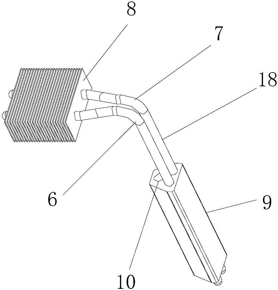
[0038] Such as figure 2 As shown, the heat-absorbing module 8 is a finned heat-exchange structure, and the heat-exchanging fins 11 are arranged parallel to the smoke exhaust direction, and there is a smoke-exhausting gap between two adjacent heat-exchanging fins 11 , and the heat-absorbing module 8 Two through-holes 10 are provided, and the heat pipe module 7 is provided with two L-shaped heat pipes 18. The heat-absorbing ends 19 of the heat pipes are connected to the through-holes 10 one by one, and the heat-absorbing ends 19 are vertically arranged with the heat exchange fins 11. Preferably, the two The distance between the heat-absorbing ends 19 of the heat pipes is 1 / 3-1 / 2 of the horizontal length of the heat exchange fins 11 , and more preferably, the distance between the heat-absorbing ends 19 of the two heat pipes is greater than the distance between the heat-emitting ends 20 .
[0039] In this embodiment, the heat release module 9 is provided with at least two through...
Embodiment 3
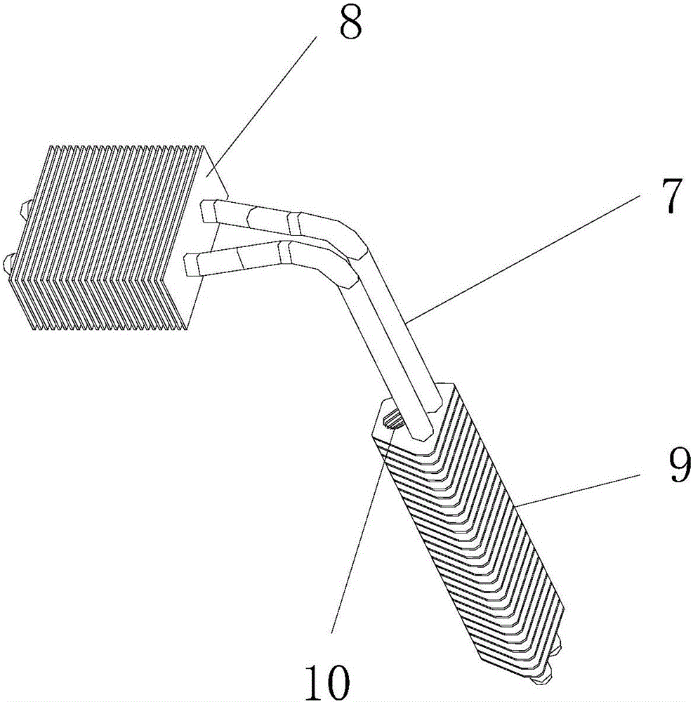
[0042] Such as image 3 As shown, the heat release module 9 in the waste heat recovery device 6 uses a finned heat exchange structure.
PUM
 Abstract
Description
Claims
Application Information
 - R&D
- Intellectual Property
- Life Sciences
- Materials
- Tech Scout
- Unparalleled Data Quality
- Higher Quality Content
- 60% Fewer Hallucinations
Browse by: Latest US Patents, China's latest patents, Technical Efficacy Thesaurus, Application Domain, Technology Topic, Popular Technical Reports.
© 2025 PatSnap. All rights reserved.Legal|Privacy policy|Modern Slavery Act Transparency Statement|Sitemap|About US| Contact US: help@patsnap.com


