
Electrical-closed decelerator accelerated life test system

An accelerated life test, reducer technology, applied in the testing of machine/structural components, machine gear/transmission mechanism testing, instruments, etc., can solve the problems of harsh working conditions, long life time, etc. The effect of improving overall performance

Inactive Publication Date: 2017-02-01
ZHEJIANG SHUANGHUAN DRIVELINE
View PDF5 Cites 9 Cited by
  • Summary
  • Abstract
  • Description
  • Claims
  • Application Information

AI Technical Summary

Problems solved by technology

[0004] The present invention aims at the disadvantages of long life time and severe working conditions in the prior art, and provides an accelerated life test system for electric enclosed reducer

Method used


Image

  • Electrical-closed decelerator accelerated life test system

Examples


Embodiment 1

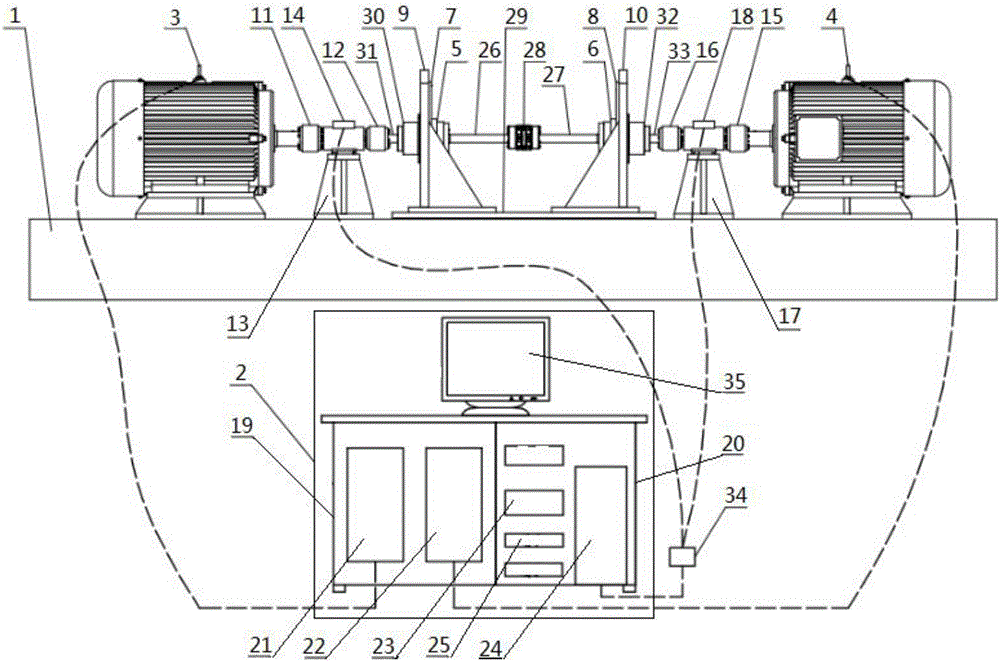
[0021] An accelerated life test system for electrically enclosed reducers, such as figure 1 As shown, the base platform 1 and the control center 2 are included, the base platform 1 is provided with a drive motor 3, and the base platform 1 is also provided with a load motor 4, a first reducer 5 and a second reducer 6, and the drive motor 3. The axis of the output shaft and the axis of the output shaft of the load motor 4 are on the same straight line. The first reducer 5 and the second reducer 6 in this embodiment are both RV reducers, and the driving motor 3 and the load motor 4 are frequency-controlled AC An asynchronous motor, the drive motor 3 is connected to the first reducer 5, the drive motor 3 is used to drive the first reducer 5, the load motor 4 is connected to the second reducer 6, the load motor 4 is used to drive the second reducer 6, and the load motor 4 is used to drive the second reducer 6. A reducer 5 is connected to the second reducer 6, and the drive motor 3 ...


PUM


Abstract

The invention relates to life test of a decelerator and discloses an electrical-closed decelerator accelerated life test system, which comprises a base platform and a control center. The base platform is provided with a driving motor. The base platform is also provided with a load motor, a first decelerator and a second decelerator. The driving motor is connected with the first decelerator; the load motor is connected with the second decelerator; the first decelerator is connected with the second decelerator; and the driving motor and the load motor are connected with the control center. The two decelerators, the transmission performance of which is same, are connected mutually to realize an effect of finishing test of the high-power decelerator through small driving power; the driving motor is used for driving the first decelerator; the load motor is used for driving the second decelerator; and the control center is used for collecting experiment data and controlling experiment output parameters.

Description

technical field [0001] The invention relates to a life test of a reducer, in particular to an accelerated life test system of an electrically enclosed reducer. Background technique [0002] The reducer is the most commonly used cycloid precision reducer, which has the advantages of compact structure, high motion precision, large transmission ratio, high load capacity, small vibration, low noise and low energy consumption, etc. It is mainly used in the joints of industrial robots , the general industrial robot has multiple degrees of freedom, and the working life of the reducer at each joint directly affects the overall working life of the industrial robot. [0003] With the continuous improvement of industrial production automation and precision, the demand for industrial robots is increasing rapidly, and it is more and more important to develop and develop high-performance reducers. In the process of R&D and manufacturing of the reducer, the life test is an important means...

Claims


Application Information

Patent Timeline
IPC IPC(8): G01M13/02
CPCG01M13/025
Inventor 张靖周莉朱忠刚
Owner ZHEJIANG SHUANGHUAN DRIVELINE
Learn More