Non-uniformity correction method and apparatus for infrared image

A non-uniformity correction, infrared image technology, applied in the field of image processing, can solve the problems of high cost, cumbersome calibration process, difficulty in real-time non-uniform correction of infrared dark spot target images, etc., and achieves low cost and strong real-time performance. Effect

Active Publication Date: 2017-02-01
CHANGCHUN INST OF OPTICS FINE MECHANICS & PHYSICS CHINESE ACAD OF SCI
View PDF3 Cites 24 Cited by
  • Summary
  • Abstract
  • Description
  • Claims
  • Application Information

AI Technical Summary

Problems solved by technology
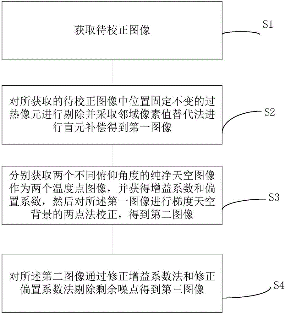
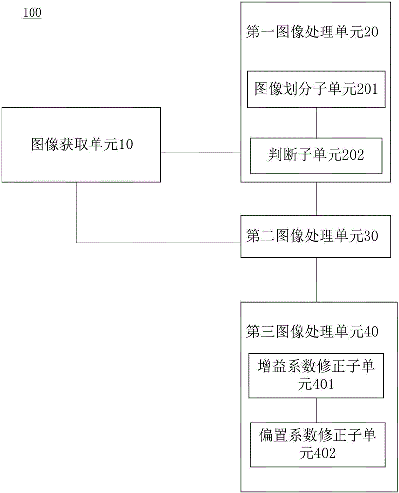
However, in the process of actually capturing the target, it is found that the blackbody radiation calibration data is not effective in correcting the non-uniformity of the actual sky background, and considering that the calibration process of the

Method used


Image

  • Non-uniformity correction method and apparatus for infrared image
  • Non-uniformity correction method and apparatus for infrared image
  • Non-uniformity correction method and apparatus for infrared image

Examples


Example Embodiment

[0031] The following describes in detail the embodiments of the present invention, examples of which are illustrated in the accompanying drawings, wherein the same or similar reference numerals refer to the same or similar elements or elements having the same or similar functions throughout. The embodiments described below with reference to the accompanying drawings are exemplary and are only used to explain the present invention, but not to be construed as a limitation of the present invention.

[0032] The following disclosure provides many different embodiments or examples for implementing different structures of the invention. In order to simplify the disclosure of the present invention, the components and arrangements of specific examples are described below. Of course, they are only examples and are not intended to limit the invention. Furthermore, the present invention may repeat reference numerals and / or letters in different instances. This repetition is for the purp...


PUM


Abstract

The invention discloses a non-uniformity correction method and apparatus for an infrared image. The non-uniformity correction method for the infrared image comprises the steps of obtaining a to-be-corrected image; removing overheated pixels with fixed positions in the obtained to-be-corrected image, and performing blind pixel compensation by adopting a neighborhood pixel value replacement method to obtain a first image; obtaining pure sky images of two different elevation angles as two temperature point images, obtaining a gain coefficient and a bias coefficient, and performing two-point method correction of a gradient sky background on the first image to obtain a second image; and removing residual noise points for the second image through a gain coefficient correction method and a bias coefficient correction method to obtain a third image. The invention furthermore discloses the non-uniformity correction apparatus for the infrared image.

Description

technical field [0001] The invention relates to the technical field of image processing, in particular to a non-uniformity correction method and device for infrared images. Background technique [0002] Infrared focal plane array (IRFPA-Infrared Focal Plane Arrays) is a new detection device developed in recent decades, which has the advantages of high sensitivity, high signal-to-noise ratio, and simple and compact structure. It is made of semiconductor materials sensitive to infrared radiation, and semiconductor materials are prone to material unevenness, mask errors, process defects, etc. during the doping process, and each pixel will inevitably produce response non-uniformity , in the form of additive or multiplicative noise, fixed patterns or random noise with uneven brightness and darkness usually appear on the image, which seriously affects the performance of the detection system. Moreover, as the service life increases, the number of blind elements will gradually incr...

Claims


Application Information

Patent Timeline
IPC IPC(8): G06T5/00
CPCG06T5/001G06T2207/10048
Inventor 王德江刘让贾平周达标
Owner CHANGCHUN INST OF OPTICS FINE MECHANICS & PHYSICS CHINESE ACAD OF SCI
Why Eureka
Try Eureka