Signal receiver, signal receiving method and multi-user multi-antenna system

A multi-user multi-antenna and receiver technology, applied in radio transmission systems, transmission systems, electrical components, etc., can solve the problem of signal receiver hardware cost and power consumption increase, system performance is difficult to meet the use requirements, and the number of signal receivers increases. and other issues, to achieve the effect of flexible and easy deployment and optimization, reducing channel training overhead, and reducing power consumption

Inactive Publication Date: 2017-02-01
UNIV OF SCI & TECH OF CHINA
View PDF3 Cites 2 Cited by
  • Summary
  • Abstract
  • Description
  • Claims
  • Application Information

AI Technical Summary

Problems solved by technology

[0003] In an ideal Massive MIMO receiver architecture, each base station antenna will be equipped with a high-quality radio frequency link and a pair of high-precision analog-to-digital converters (Analog-to-Digital Converter, ADC); however, as the number of base station antennas increases With a substantial increase, the number of high-precision ADCs required by the signal receiver will also increase significantly, which means that the hardware cost and power consumption of the signal receiver will increase significantly, which may become the main bottleneck restricting the large-scale commercial use of Massive MIMO
Although the single-bit ADC has the advantages of low power consumption and low cost, it has long been an important choice for the design of low hardware complexity receivers in wireless communication systems, but the signal receiver composed of single-bit ADCs will face serious spectrum constraints when applied to Massive MIMO systems. Efficiency loss, making it difficult for system performance to meet usage requirements

Method used


Image

  • Signal receiver, signal receiving method and multi-user multi-antenna system
  • Signal receiver, signal receiving method and multi-user multi-antenna system
  • Signal receiver, signal receiving method and multi-user multi-antenna system

Examples


Embodiment Construction

[0042] The following will clearly and completely describe the technical solutions in the embodiments of the present invention with reference to the accompanying drawings in the embodiments of the present invention. Obviously, the described embodiments are only some, not all, embodiments of the present invention. Based on the embodiments of the present invention, all other embodiments obtained by persons of ordinary skill in the art without making creative efforts belong to the protection scope of the present invention.

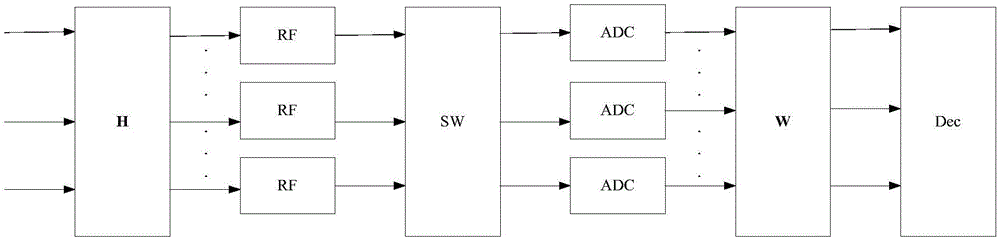
[0043] An embodiment of the present application provides a signal receiver, which is applied to a multi-user multi-antenna system. The multi-user multi-antenna system includes a base station and U users, the base station has N antennas, and each user has a Antenna, the uplink channel from user u to base station is denoted as h u =[h 1u ,..., h Nu ] T , the uplink channel from all users to the base station is recorded as the channel matrix H=[h 1 ,..., h U...


PUM


Abstract

The application discloses a signal receiver, a signal receiving method and a multi-user multi-antenna system. N pairs of ADCs configured by the signal receiver comprise K pairs of high-precision ADCs and N-K pairs of single-bit ADCs. Compared with an ideal signal receiver composed of all high-precision ADCs, the signal receiver has the advantage of lower cost. The K pairs of high-precision ADCs are switched by an ADC switching module, so that the K pairs of high-precision ADCs are fully utilized, spectrum efficiency loss caused by single bit quantification is reduced, the channel training cost is lowered significantly, and the bit error rate performance of the multi-user multi-antenna system is improved greatly. Therefore, the cost and power consumption of the signal receiver are reduced on the basis of meeting the performance requirement of the multi-user multi-antenna system. Moreover, the signal receiver is flexible to deploy and optimize and easy to implement, and is especially applicable to a massive multi-user multi-antenna system or a millimeter wave system.

Description

technical field [0001] The present application relates to the technical field of wireless communication, and more specifically, to a signal receiver, a signal receiving method and a multi-user multi-antenna system. Background technique [0002] According to the "International Institute of Electrical and Electronics Engineers Wireless Communications Journal" (IEEE Trans.Wireless Commun., vol.9, no.11, pp.3590–3600, 2010.), by configuring a large-scale antenna array in the base station and Serving multiple users on the same time-frequency resource block at the same time, the Massive Multiple-Input Multiple-Antenna System (Massive Multiple-Input Multiple-Output) can greatly improve the spectral efficiency and radiation energy efficiency of the cellular network, so it is recognized as the fifth generation of mobile One of the key technologies of communication. [0003] In an ideal Massive MIMO receiver architecture, each base station antenna will be equipped with a high-quality...

Claims


Application Information

Patent Timeline
Patent Type & Authority Applications(China)
IPC IPC(8): H04B7/0452H04B1/00H04B1/30
CPCH04B7/0452H04B1/0007H04B1/0028H04B1/30H04B2001/307
Inventor 梁宁张文逸陈晓辉
Owner UNIV OF SCI & TECH OF CHINA
Why Eureka
Try Eureka