Bending automatic polishing machine
An automatic polishing and pipe bending technology, which is applied in the field of pipe fittings processing, can solve the problems of uneven polishing, inability to polish multi-joint pipe bends, poor quality, etc., and achieve the effects of convenient and fast operation, improved polishing operation efficiency, and high production efficiency
- Summary
- Abstract
- Description
- Claims
- Application Information
AI Technical Summary
Problems solved by technology
Method used
Image
Examples
Embodiment 1
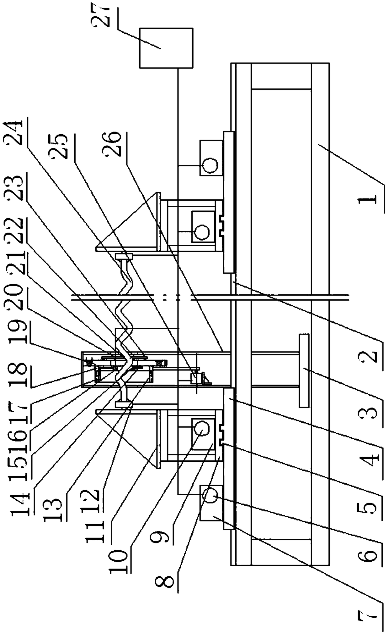
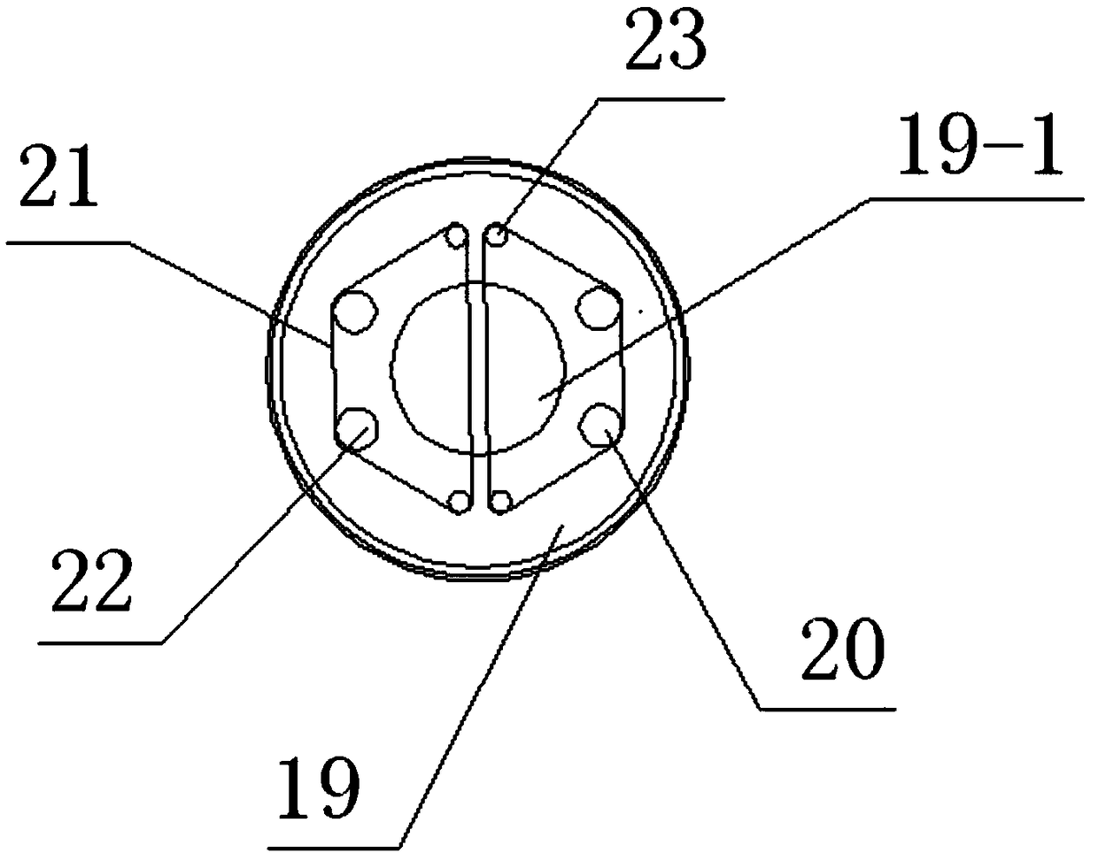
[0029] Such as figure 1 , figure 2 As shown, the automatic elbow polishing machine of the present invention includes a machine base 1 , a composite rotary polishing device, an elbow feeding device and a controller 27 , and the composite rotary polishing device is fixedly installed on the bottom plate of the machine base 1 . The top of the machine base 1 is provided with a longitudinal guide rail 2, and the bent pipe feeding device is located on the top of the machine base 1, and it has two manipulators respectively located at both ends of the machine base 1. The longitudinal guide rail 2 moves left and right. The manipulator includes a pallet 4, a support 8, a first chuck support 11 and a pneumatic chuck 12 connected in sequence from bottom to top, the pallet 4 is provided with a transverse guide rail 5, the pallet 3 and the lateral guide rail 5 Slidingly connected, it can move forward and backward along the transverse guide rail 5. A longitudinal movement drive mechanism ...
Embodiment 2
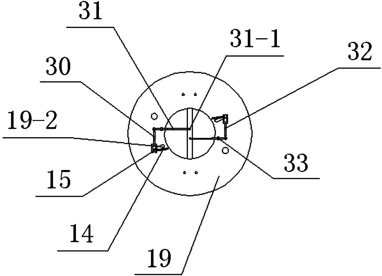
[0034] see image 3 As a further improvement of the present invention, the rotating disk 19 is provided with an automatic opening mechanism for two abrasive belts, and the mechanism has a lever-type driving lever 30, which is movably connected with the rotating disk 19 through a pin 32, and its two A shift fork structure is arranged at one end of the shift rod 30. The shift fork at one end of the shift rod 30 is slidably connected with a pull rod 31. The pull rod 31 can be flexibly connected with the rotating disc 19 through a seat cover 33. The front end of the pull rod 31 is provided with a claw 31-1, and the claw 31-1 Located between the two abrasive belts 21 , the shift fork at the other end is movably connected with the axle 15 of the tensioning wheel 22 . When the rotating disk 19 stops rotating, the wheel shaft 15 of the tensioning wheel 22 moves to the nearest end of the long slotted hole 19-2 to the axis of the rotating disk 19 under the pulling force of the spring 14, ...
Embodiment 3
[0036] see Figure 4 , Figure 5 , Figure 6 , Figure 7 , in order to realize full automation of the elbow polishing operation, the first chuck support 11 is movably connected with the support 8 through the turntable 28, and the turntable 28 is connected with a fifth servo motor 29. The polishing machine 100 is equipped with a feeding device, which includes a feeding manipulator 200 and a conveyor 300, and the feeding manipulator 200 includes a base 34, a support 37, a second chuck support 38 and a pneumatic chuck 39 connected in sequence, A turntable 41 and a sixth servo motor 42 connected to the turntable 41 are arranged at the bottom of the second chuck support 38 , and the servo motor 42 is connected to the controller 27 for signals. A lifting mechanism can be set between the support 37 and the base 34, and the lifting mechanism includes a lifting cylinder 35, a guide column 36, a lifting limit rod 44 and upper and lower limit nuts 43, 45 connected with the limit rod 4...
PUM
 Abstract
Description
Claims
Application Information
 - R&D
- Intellectual Property
- Life Sciences
- Materials
- Tech Scout
- Unparalleled Data Quality
- Higher Quality Content
- 60% Fewer Hallucinations
Browse by: Latest US Patents, China's latest patents, Technical Efficacy Thesaurus, Application Domain, Technology Topic, Popular Technical Reports.
© 2025 PatSnap. All rights reserved.Legal|Privacy policy|Modern Slavery Act Transparency Statement|Sitemap|About US| Contact US: help@patsnap.com


