
Composite shape correction method for tooth contour of cycloidal gear of RV reducer

A technology of cycloidal wheel and reducer, which is applied in the direction of gear teeth, components with teeth, belts/chains/gears, etc. It can solve the problems of conjugated tooth profile, large force at the meshing point, and small number of tooth pairs. Achieve the effects of compensating installation errors, reducing stress concentration, improving bearing capacity and transmission accuracy

Inactive Publication Date: 2017-02-15
CHONGQING UNIV
View PDF3 Cites 11 Cited by
  • Summary
  • Abstract
  • Description
  • Claims
  • Application Information

AI Technical Summary

Problems solved by technology

The tooth profile modified by the corner and the needle tooth form a conjugate tooth profile. At the same time, the number of meshing teeth is half of the number of needle teeth in theory, but it cannot form a radial clearance at the root and top of the tooth, which cannot compensate for manufacturing errors and meet lubrication requirements
At present, in the design of the cycloidal wheel of the RV reducer, most of them adopt the method of combined modification of equidistant plus displacement to approach the method of corner modification. Although this method can produce a certain gap at the root and top of the tooth, However, its working tooth profile section cannot form a conjugate tooth profile with the needle teeth in theory. On the one hand, the number of tooth pairs participating in meshing at the same time is too small, and the force on the meshing part is relatively large, which is not conducive to the bearing capacity and life of the reducer. , on the other hand, the accurate transmission ratio cannot be guaranteed, which will have an adverse effect on the transmission accuracy of the reducer

Method used


Image

  • Composite shape correction method for tooth contour of cycloidal gear of RV reducer
  • Composite shape correction method for tooth contour of cycloidal gear of RV reducer
  • Composite shape correction method for tooth contour of cycloidal gear of RV reducer

Examples


Embodiment

[0034] This embodiment implements compound modification to the RV-40E type reducer cycloidal wheel used by the robot. The specific steps are as follows:

[0035] Step 1. Determine the tooth profile range of the working section of the cycloidal wheel

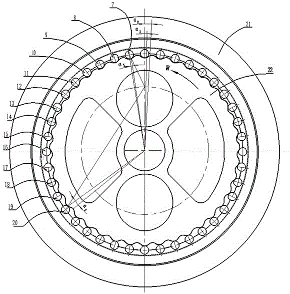
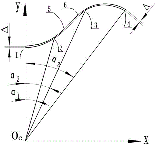
[0036] According to the requirements of transmission stability and carrying capacity, the number of teeth that the cycloidal wheel participates in meshing at the same time is initially determined when the RV reducer is working. Such as figure 1 As shown, the RV-40E reducer includes a pin gear housing 21, a standard cycloid wheel 22, and 40 pin teeth. The initial pin tooth number 7 and the final pin tooth number 20 of the cycloid wheel participate in the meshing, and the corresponding meshing Phase angle α 1 =0.0112, α 2 = 0.0591 is the position of the two boundary points of the working part of the cycloid gear profile, and the meshing phase angle range of the gear profile of the cycloid gear working section is [α 1 , α 2 ]. ...


PUM


Abstract

The invention discloses a composite shape correction method for the tooth contour of a cycloidal gear of an RV reducer. The method comprises the following steps of 1, determining the tooth contour scope of a work section of the cycloidal gear; 2, according to the corner shape correction mode, determining a tooth contour curve of the work section of the cycloidal gear out of the tooth contour scope, obtained in step 1, of the work section of the cycloidal gear; 3, determining tooth contour curves of a tooth top section and a tooth root section of the cycloidal gear; and 4, according to a tooth contour curve equation, obtained in step 2 and step 3, of the work section, the tooth top section and the tooth root section of the cycloidal gear and a region corresponding to the tooth contour curve equation, obtaining a tooth contour curve of the cycloidal gear obtained after composite shape correction based on MATLAB. The composite shape correction method has the beneficial effects that carrying capacity of the RV reducer is increased, and transmission precision of the RV reducer is improved.

Description

technical field [0001] The invention belongs to RV reducers, and in particular relates to a compound modification method for the tooth profile of a cycloid wheel of an RV reducer. Background technique [0002] RV reducer is a precision transmission device developed on the basis of cycloidal pinwheel transmission, which includes a first-stage involute planetary gear train and a first-stage cycloidal pinwheel planetary gear train. Among them, the cycloid planetary mechanism directly connected to the output mechanism at a low speed stage plays a key role in the transmission accuracy and life of the entire RV reducer. [0003] The standard cycloidal pinwheel drive theoretically belongs to backlash-free meshing, and the number of teeth participating in the meshing is half of the number of pinwheel teeth. However, due to processing and installation errors and elastic deformation of each component of the gear train, if a standard cycloidal wheel is used to mesh with the pin wheel,...

Claims


Application Information

Patent Timeline
Patent Type & Authority Applications(China)
IPC IPC(8): B23F15/00
CPCB23F15/00
Inventor 杜雪松余自强朱才朝宋朝省
Owner CHONGQING UNIV
Learn More