
Charging power distribution method and system for energy storage type urban rail train

An urban rail train and charging power technology, which is applied in the field of charging power distribution methods and systems for energy storage urban rail trains, can solve the problem that the power of the traction system rises and the power of the ground power supply device cannot meet the power requirements of the traction system auxiliary system and the air conditioning system at the same time. and other problems to achieve the effect of reducing construction costs

Active Publication Date: 2017-02-15
ZHUZHOU CSR TIMES ELECTRIC CO LTD
View PDF6 Cites 10 Cited by
  • Summary
  • Abstract
  • Description
  • Claims
  • Application Information

AI Technical Summary

Problems solved by technology

However, in the stage of train traction starting and accelerating out of the station, if the power of other systems of the train remains unchanged under the catenary power supply in the stop area, the power of the traction system will continue to rise with the acceleration of starting, resulting in the power of the ground power supply device being unable to meet the requirements of the traction system, Power requirements of on-board energy storage charging system, auxiliary system and air conditioning system

Method used


Image

  • Charging power distribution method and system for energy storage type urban rail train
  • Charging power distribution method and system for energy storage type urban rail train
  • Charging power distribution method and system for energy storage type urban rail train

Examples


Embodiment Construction

[0037] The present invention will be further described below in conjunction with the accompanying drawings and specific preferred embodiments, but the protection scope of the present invention is not limited thereby.

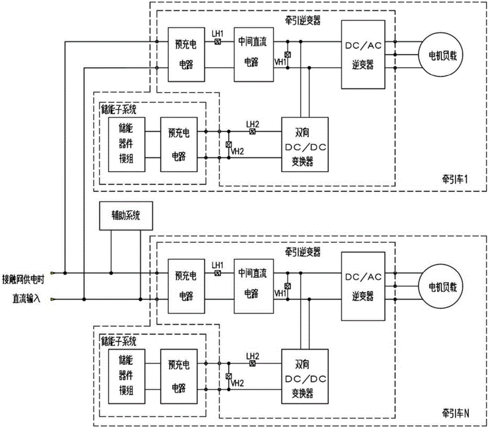
[0038] Such as figure 1 As shown, the energy storage type urban rail train of this embodiment includes multiple tractors, numbered as tractor 1 to tractor N, and each tractor has a set of traction system, including traction inverter part, traction motor (motor load) and energy storage devices. The traction motor is powered by a DC / AC inverter, and the energy storage device is charged by a bidirectional DC / DC converter. The DC / AC inverter and the bidirectional DC / DC converter are connected in parallel through an intermediate DC circuit. The traction system of each tractor is connected in parallel through the DC input bus powered by catenary, and the auxiliary system of the train is connected in parallel with the DC input bus powered by catenary.

[0039] Such a...


PUM


Abstract

The invention discloses a charging power distribution method and a charging power distribution system for an energy storage type urban rail train. The method comprises the following steps: S1, acquiring the maximum allowable output current limit value of a ground charging device; S2, acquiring an auxiliary-power-supply real-time current value of a train assistance system; S3, calculating a traction-power-supply maximum allowable current value; S4, calculating a traction real-time current value; S5, calculating the maximum charging current limit value according to the traction-power-supply maximum allowable current value and the traction real-time current value; and S6, charging an energy storage device within the range of the maximum charging current limit value. The system comprises a parameter acquisition module, a traction calculation module, a calculation module and a charging control module. By reasonable distribution of the power required by charging of a traction system and an energy storage system of the train, the charging power distribution method and the charging power distribution system have the advantages that the power requirement of the train on the ground charging device can be easily and efficiently reduced, so that the construction cost of the ground charging device is reduced.

Description

technical field [0001] The invention relates to the field of charging control for energy storage urban rail trains, in particular to a charging power distribution method and system for energy storage urban rail trains. Background technique [0002] Some new urban rail trains represented by low-floor trams usually use energy storage station stop power supply, that is, there is no catenary power supply in the station operating section, and the electric energy required for train operation is provided by the on-board energy storage system through two-way DC- DC converter step-up chopper provides power supply for the train traction system (including traction subsystem and energy storage device), auxiliary system and air-conditioning system through the ground power supply device installed at each station when the station stops. Each station is usually equipped with a set of ground power supply devices. In order to save construction costs, the power of the ground power supply devic...

Claims


Application Information

Patent Timeline
IPC IPC(8): B60L9/18B61C3/00H02J7/00
CPCB60L9/18B60L2200/26B60L2210/10B60L2210/44B61C3/00H02J7/00
Inventor 袁红霞袁文烨陈文光夏文杰刘良杰陈新溅肖健付玉豪许义景张路军
Owner ZHUZHOU CSR TIMES ELECTRIC CO LTD
Features
  • Generate Ideas
  • Intellectual Property
  • Life Sciences
  • Materials
  • Tech Scout
  • Unparalleled Data Quality
  • Higher Quality Content
  • 60% Fewer Hallucinations
Learn More