
An oil tank heater with a valve

A heater and oil tank technology, applied in the field of oil tank heaters, can solve the problems of working environment pollution, prolonging maintenance time, pollution, etc., and achieve the effects of increasing heat exchange area, reducing circulation area, and ensuring heat transfer efficiency

Active Publication Date: 2018-07-03
SHANDONG PULILONG PRESSURE VESSEL
View PDF5 Cites 0 Cited by
  • Summary
  • Abstract
  • Description
  • Claims
  • Application Information

AI Technical Summary

Problems solved by technology

The temperature of the oil near the heater is high, and the temperature of the oil far away from the heater is low, which seriously affects the fluidity of the oil
[0007] Affect oil quality
Repeated heating of the oil in the oil tank will produce a large number of fine decomposition products during the heating process, which will have a certain impact on the color quality of the oil and increase the cost of post-processing
[0008] During the use of the built-in oil tank heater, since the tube bundle is inserted into the oil storage tank as a whole, and the medium in the tube is steam, due to metal corrosion, medium scouring and other reasons, it may cause local cracks, pores and other leakage phenomena in the heat exchange tube. , after the rupture, the steam moisture will enter the oil in the storage tank, because the leakage point is inside the equipment, and there are no other effective monitoring methods, it is difficult to detect it in time by manual inspection
Although the probability of leakage is extremely small, once it is leaked, it will bring huge losses to users
Since the lubricating oil has extremely strict requirements on moisture, when the heater in the storage tank leaks, the moisture in the lubricating oil in the storage tank exceeds the standard. Because the cost of treating the lubricating oil moisture is high, it is generally not necessary to treat the moisture exceeding the standard. The lubricating oil is processed, and the lubricating oil is directly returned to the factory, which not only causes a waste of energy, but also pollutes the environment
[0009] In addition, the built-in oil tank heater is directly inserted into the oil tank through the through hole at the lower end of the oil tank, sealed and then fed into the oil for heating. The tank is pulled out and repaired. At this time, if there is oil in the tank, the oil in the tank must be exported, which increases the workload and prolongs the maintenance time; at the same time, the oil will also flow out from the hole of the tank. Cause waste and pollution of oil products, and also pollute the working environment

Method used


Image

  • An oil tank heater with a valve
  • An oil tank heater with a valve
  • An oil tank heater with a valve

Examples


Embodiment 1

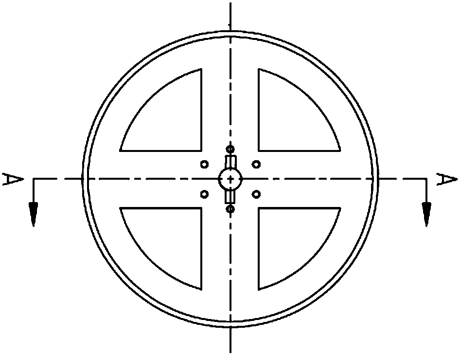
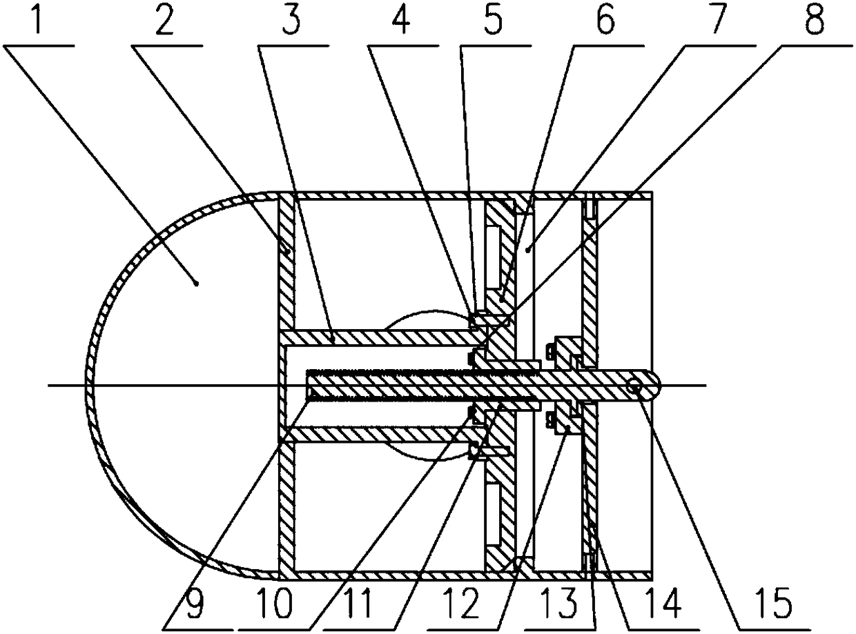
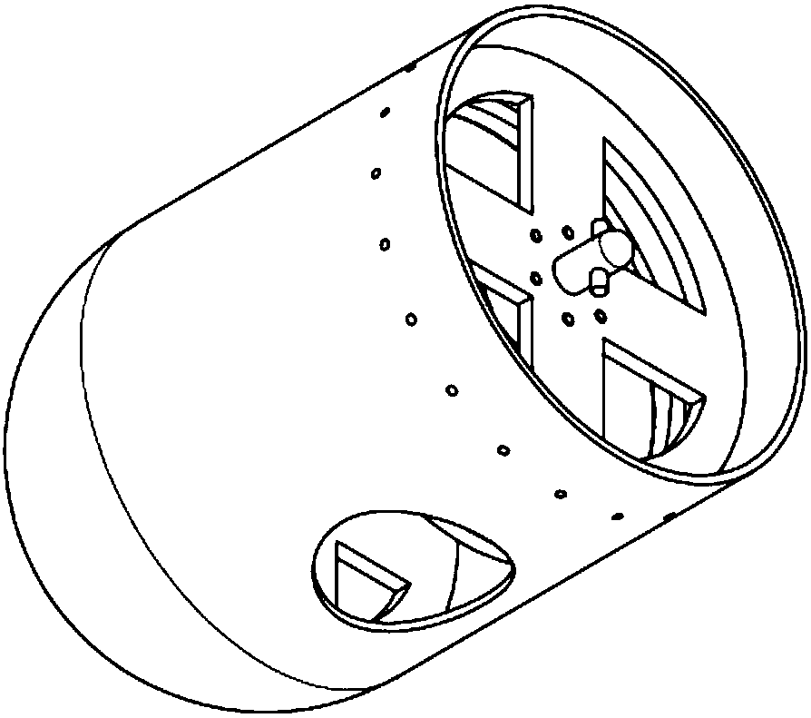
[0055] Such as figure 2 , image 3 and Figure 7 As shown, an oil tank heater with a valve includes a housing 19, a heating component and a valve structure. The heating component includes several heating tube bundles and a heater head 17 that fixes the heating tube bundle. The heater head and The housing 19 cooperates to fix the heating tube bundle inside the housing 19. The heating tube bundle is fixed together by a stainless steel cluster. The heater head 17 is provided with an oil outlet, and the tail of the housing is provided with an oil suction port. The valve The structure is arranged at the tail of the shell;

[0056] The valve structure includes a front fixed base 14, a rear fixed base 2 and a movable valve body. The front fixed base 14 and the rear fixed base 2 are respectively located on both sides of the oil suction port, and the front fixed base 14 is located at the rear fixed base. Between seat 2 and the heater head.

[0057] The movable valve body is positi...

Embodiment 2

[0074] Such as Figure 4 , Figure 5 and Figure 6 As shown, the movable valve body includes a bottom and a side wall, the bottom has a hole, the side wall of the movable valve body is attached to the inner wall of the housing 19, and the side wall is provided with an opening corresponding to the oil suction port. , the length of the solid portion of the side wall is greater than the diameter of the oil suction port.

[0075] Shake the drive handle 16 to drive the drive shaft 18 to rotate, and then drive the transmission screw 9 to rotate, the movable valve body moves to the front fixed base 14 under the drive of the transmission screw 9, and the side wall of the movable valve body moves the heater shell The oil suction port of 19 is blocked, prevents that the oil in the oil tank flows out from the oil suction port.

[0076] After the heater has been repaired, the heater is installed in the oil tank, and the two are sealed, and the drive handle 16 is shaken to drive the dri...


PUM


Abstract

The invention discloses an oil tank heater with a valve. The oil tank heater comprises a shell, a heating component and a valve structure, wherein the heating component comprises a plurality of heating tube bundles and a heater head which is used for fixing the heating tube bundles, and the valve structure is arranged at the tail of the shell; the valve structure comprises a front fixed base, a back fixed base and a movable valve body, the front fixed base and the back fixed base are respectively located on both sides of an oil suction port, and the front fixed base is located between the back fixed base and the heater head; and the movable valve body is located between the front fixed base and the back fixed base, a threaded hole is formed in the front end of the movable valve body, a driving screw is installed on the front fixed base, one end of the driving screw is matched with the threaded hole, a bulge clamping structure is arranged on the other end of the driving screw, a driving shaft penetrates through the heater head, a driving handle is arranged on the outer end of the driving shaft, the inner end of the driving shaft extends to the front fixed base, and a groove which is matched with the bulge clamping structure is formed in the inner end of the driving shaft.

Description

technical field [0001] The invention belongs to the technical field of pipeline measurement and control, and in particular relates to an oil tank heater with a valve. Background technique [0002] At present, in the process of oil storage and transportation, the heating of the oil in the tank basically adopts traditional methods such as installing tubular or coil heaters in the tank, so that the oil in the tank passes through the heat medium (usually saturated The exchange of steam as the heat medium can realize the temperature rise of the oil, reduce the viscosity and improve its fluidity, so as to facilitate the transportation of the pump. This traditional heating method has the following disadvantages: [0003] The heat exchange efficiency is low and the steam consumption is large. The heating of the oil by the traditional internal heater is a static natural convection heat transfer, and its heat release coefficient is extremely low. Due to low heat transfer efficiency...

Claims


Application Information

Patent Timeline
Patent Type & Authority Patents(China)
IPC IPC(8): B65D88/74
CPCB65D88/744
Inventor 边荣江赵连勤王锦迟焕磊傅乃国王风驰
Owner SHANDONG PULILONG PRESSURE VESSEL
Learn More