
H+T type component and combination beam of H+T type component and floor

A technology of combining beams and components, applied in floors, building components, buildings, etc., can solve the problems of steel beam material waste, reduce indoor clearance, increase beam height, and improve flexural bearing capacity, flexural rigidity, and beam steel consumption. reduced effect

Inactive Publication Date: 2017-02-15
江苏拓特智能制造有限公司 +1
View PDF6 Cites 5 Cited by
  • Summary
  • Abstract
  • Description
  • Claims
  • Application Information

AI Technical Summary

Problems solved by technology

However, in actual engineering design, the effect of composite beams is often not considered accurately and fully utilized; and in actual design, in order to simplify the calculation, sometimes the increase in the flexural rigidity and flexural capacity of the floor to the beam is not considered, resulting in the Waste of material, increased beam height, reduced interior headroom

Method used


Image

  • H+T type component and combination beam of H+T type component and floor
  • H+T type component and combination beam of H+T type component and floor
  • H+T type component and combination beam of H+T type component and floor

Examples


Embodiment 1

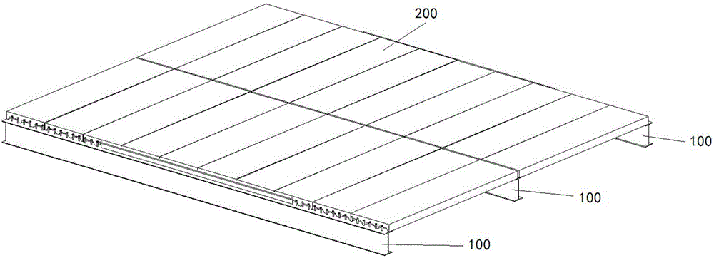
[0025] figure 1 It is a perspective view of the H+T-shaped component and the floor composite beam in the first embodiment.

[0026] Such as figure 1 As shown, the H+T-shaped component and floor composite beam includes: three H+T-shaped components 100 and a concrete floor assembly 200 .

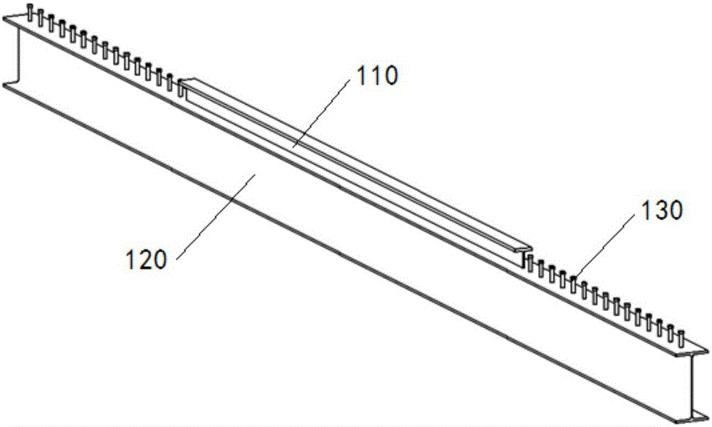
[0027] figure 2 It is a perspective view of the H+T-shaped component in Embodiment 1.

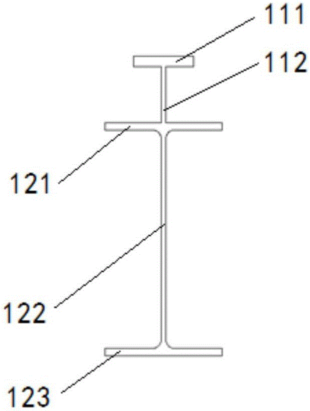
[0028] image 3 It is a cross-sectional view of an H+T-shaped component in Embodiment 1.

[0029] Such as figure 2 and image 3 As shown, the H+T-shaped component includes: a T-shaped bar 110 , an H-shaped bar 120 and several shear keys 130 .

[0030] The T-profile 110 comprises an upper flange 111 and a web 112 . The H-profile 120 includes an upper flange 121 , a web 122 and a lower flange 123 . The upper flange 111 of the T-shaped bar is parallel to the two flanges 121, 123 of the H-shaped bar, the web 112 of the T-shaped bar is in a straight line with the web 122 of the H-shaped bar, and the T...

Embodiment 2

[0039] Figure 5 It is a perspective view of the H+T-shaped component and the floor composite beam in the second embodiment.

[0040] Such as Figure 5 As shown, the H+T-shaped component and floor composite beam includes: three H+T-shaped components 100 and a concrete floor assembly 200 .

[0041] Figure 6 It is a perspective view of the H+T-shaped component in Embodiment 2.

[0042] Such as Figure 6 As shown, the T-shaped bar 110 of the H+T-shaped component 100 is long, and no shear key 130 is provided. The other parts are the same as those in the first embodiment, and will not be described again.

[0043] The H+T-shaped component and the floor composite beam in this embodiment are particularly suitable for use as a structural main beam.

[0044] The H+T components in Embodiment 1 and Embodiment 2 can be used in any combination with the concrete floor assembly.


PUM


Abstract

The invention provides an H+T type component which comprises T type proximate matter and H type proximate matter. The flange of the T type proximate matter is parallel to the two flanges of the H type proximate matter, a web of the T type proximate matter and a web of the H type proximate matter are located in one straight line, the T type proximate matter is fixed to the H type proximate matter, or the T type proximate matter and the H type proximate matter are integrally molded. The invention further provides a combination beam of the H+T type component and a floor. The combination beam comprises the H+T type component and a floor assembly; and the floor assembly comprises at least one layer of reinforcing steel bars, and the reinforcing steel bars are fixed to the T type proximate matter. The H+T type component and the combination beam have the beneficial effects that under the condition that the building layer height, the beam span and the load are the same, the effective section depth is larger than that of a traditional H type cross section, and the flexural rigidity and the flexural capacity of beams can be effectively improved; and the beam height is reduced, the indoor using clear height is increased, the steel using amount of the beams is reduced, and the aims of being economical and applicative can be achieved.

Description

technical field [0001] The invention relates to an H+T-shaped component and a combined beam of the H+T-shaped component and a floor slab, which belongs to the field of building structures and is mainly applied to secondary beams and main beams of steel structures or secondary beams in concrete structures. Background technique [0002] In the building structure, the combined force between the steel beam and the floor slab makes the bending stiffness and bending bearing capacity of the composite beam significantly greater than that of the steel beam. However, in actual engineering design, the effect of composite beams is often not considered accurately and fully utilized; and in actual design, in order to simplify the calculation, sometimes the increase in the flexural rigidity and flexural capacity of the floor to the beam is not considered, resulting in the The waste of materials increases beam height and reduces interior headroom. In order to make full use of the steel bea...

Claims


Application Information

Patent Timeline
Patent Type & Authority Applications(China)
IPC IPC(8): E04B5/10
CPCE04B5/10
Inventor 彭礼王明兴董远亮赵敦实曹堰纲
Owner 江苏拓特智能制造有限公司
Learn More