Underwater anti-blocking and resistance-reducing elbow structure

A pipe bending and anti-blocking technology, which is applied in the direction of elbows, siphons, pipe components, etc., can solve the problems of inner wall wear of pipe fittings, large water flow resistance of ordinary pipe fittings, and pipe fitting blockage, so as to enhance the swirling effect, avoid solid particle deposition, The effect of preventing clogging of elbows

Inactive Publication Date: 2017-02-15
泰州学院
View PDF8 Cites 3 Cited by
  • Summary
  • Abstract
  • Description
  • Claims
  • Application Information

AI Technical Summary

Problems solved by technology

It is well known that petroleum, hydrate, ore and other resources contain particulate matter. During the flow process, the particles will settle due to the influence of the gravity of the particles. Common pipe fittings have the following disadvantages when transporting such media: After the fluid containing particulate matter enters the ordinary pipe fittings, due to the gravity Influenced by the influence of high-density particles, the velocity decreases and settles, the fluid moves in the center of the pipe fittings, and the particles move at the bottom of the pipe fittings. As the particle velocity continues to decrease, the particles at the bottom of the pipe fittings accumulate, which not only leads to blockage of the pipe fittings but also causes pipe fittings Premature wear of the inner wall; the pipe fittings are used underwater, especially in the marine environment. Due to the viscosity of the water flow, a boundary layer is formed when the water flows through the outer surface of the pipe fitting. The greater the water velocity, the thicker the boundary layer, and the thickness of the boundary layer reaches a certain level The surface of the pipe is separated from the surface of the pipe, forming a boundary layer separation, resulting in the formation of a symmetrical vortex behind the pipe. The larger the vortex area, the smaller the pressure, and the pressure of the water flow in front of the pipe is high, so the pressure difference between the front and back of the pipe is formed, resulting in resistance; ordinary pipes are smooth On the surface, this kind of boundary layer separates early, the vortex area formed behind the pipe fitting is small, and the pressure difference between the front and back of the pipe fitting is large, resulting in large water flow resistance of ordinary pipe fittings underwater

Method used


Image

  • Underwater anti-blocking and resistance-reducing elbow structure
  • Underwater anti-blocking and resistance-reducing elbow structure
  • Underwater anti-blocking and resistance-reducing elbow structure

Examples


Embodiment Construction

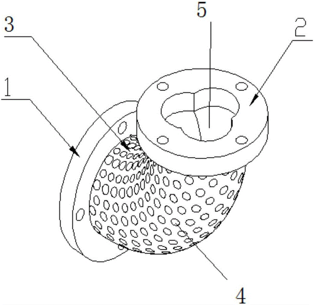
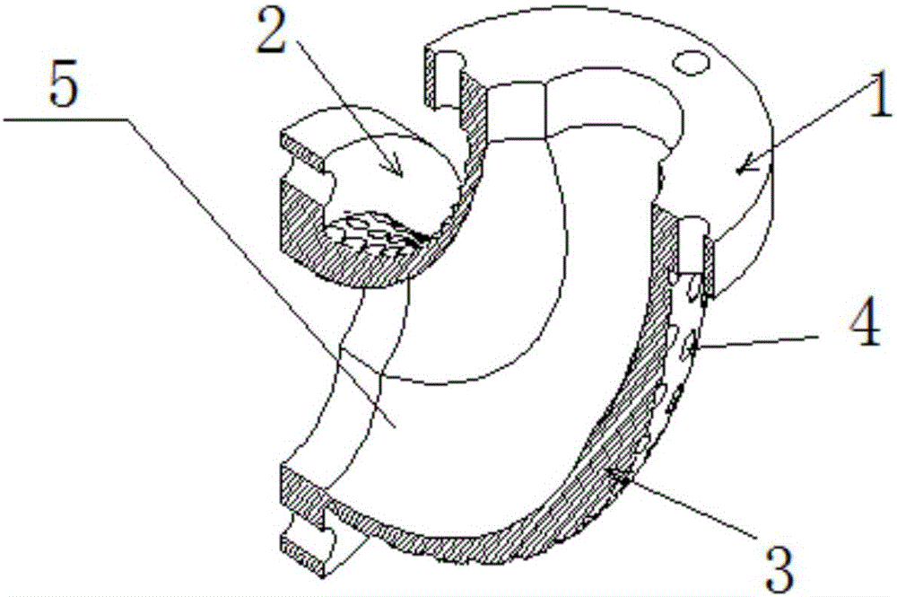
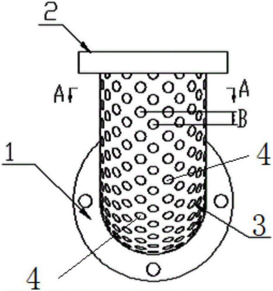
[0028] As shown in the drawings, an underwater elbow structure for anti-clogging and drag reduction includes an elbow 3 , an inlet flange 1 and an outlet flange 2 arranged at both ends of the elbow 3 .

[0029] A plurality of spiral grooves 5 are arranged inside the flow channel of the elbow 3 along its length direction, and a plurality of pits 4 are formed on the outer surfaces of the main pipe section 3 and the transition section 2 respectively. The spiral groove 5 is used to prevent particles from clogging the elbow 3 . Dimples 4 are used to reduce hydraulic resistance.

[0030] In this embodiment, the angle of the elbow 3 is 90 degrees, the outer diameter of the elbow 3 is 110 millimeters, the length from the center of the elbow 3 to the end face is 120 millimeters, and the hydraulic diameter of the inner spiral groove 5 of the elbow 3 is 80 millimeters. The outer diameter of the flange 1 and the outlet flange 2 is 229 mm, the inner diameter of the flange is 102 mm, and t...


PUM


Abstract

An underwater anti-blocking and resistance-reducing elbow structure comprises an elbow as well as an inlet flange and an outlet flange which are arranged at two ends of the elbow; multiple spiral grooves are formed in a flow channel of the elbow in the length direction of the channel; and multiple pits are formed in the outer surface of a main pipe section and the outer surface of a switching section respectively. When the structure is used for conveying a particle-containing fluid in an underwater environment, the multiple spiral grooves are machined in the elbow to enhance the rotational flow effect of the fluid in the elbow, the particle-containing fluid rotates in the flow channel of the elbow, the rotational flow acting force is applied to particles, the particles are in the suspended state, deposition of solid particles due to the secondary flow effect of the elbow is avoided, and the particles are effectively prevented from blocking the elbow; and the surface pits are formed in the outer surface of the elbow, so that resistance produced by flow boundary layer separation is reduced.

Description

technical field [0001] The invention relates to an underwater elbow structure for preventing blocking and reducing drag. Background technique [0002] The rapid development of the global economy and the shortage of land resources have promoted the development process of marine mineral resources. At present, the well-known marine mineral resources include oil, placer, combustible ice, manganese metal nodules, etc. For the development of such resources, its important The step is the delivery process of the pipe fittings. It is well known that petroleum, hydrate, ore and other resources contain particulate matter. During the flow process, the particles will settle due to the influence of the gravity of the particles. Common pipe fittings have the following disadvantages when transporting such media: After the fluid containing particulate matter enters the ordinary pipe fittings, due to the gravity Influenced by the influence of high-density particles, the velocity decreases an...

Claims


Application Information

Patent Timeline
Patent Type & Authority Applications(China)
IPC IPC(8): F16L55/045F16L43/00
CPCF16L55/045F16L43/00
Inventor 王健丁剑刘厚林赵振江宋向前王临茹郭沁涵
Owner 泰州学院
Why Eureka
Try Eureka