

Multistage demisting device
A technology of demisting equipment and demisting components, which is applied in the direction of separation devices, membrane technology, and dispersed particle separation, can solve the problems of difficult processing, complex technical structure, and high processing and manufacturing costs, so as to reduce mist entrainment and realize air pollution. Liquid separation, not easy to scale effect
Active Publication Date: 2018-10-23
CHINA PETROLEUM & CHEM CORP +1
View PDF13 Cites 2 Cited by
- Summary
- Abstract
- Description
- Claims
- Application Information
AI Technical Summary
Problems solved by technology
During the separation process of the liquid phase and the gas phase of this technology, gas-liquid cross flow can be realized, so the secondary entrainment effect of the gas relative to the liquid droplet is greatly reduced, but the technical structure is very complicated, the processing difficulty is relatively large, and the corresponding processing and production costs are relatively high.
Method used
View moreImage
Smart ImageViewing Examples

Examples
Embodiment 1
[0066] A wet scrubber purifies flue gas 100000Nm 3 / h, where the apparent water concentration is 10-15g / Nm 3 , after demisting by the present invention, the apparent water concentration in the exhaust gas is less than 0.5g / Nm 3 , Demist efficiency ≥ 95%.
Login to View More PUM
 Abstract
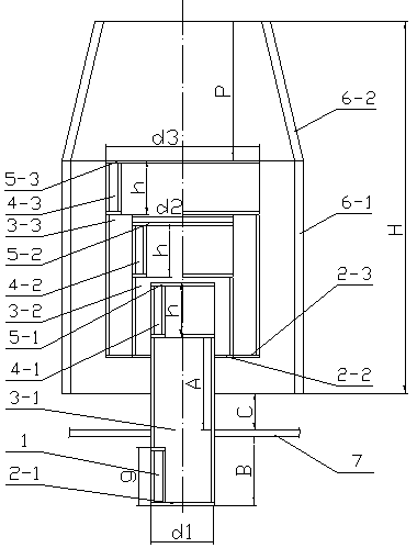
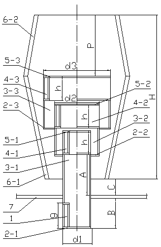
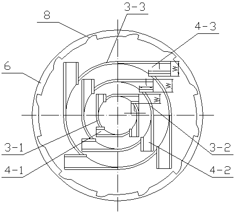
The invention discloses a multistage demisting device. The multistage demisting device comprises a plurality of parallel demisting assemblies, each of the demisting assemblies comprises multistage risers and an outer cylinder, the multistage risers are multiple coaxial risers with the caliber gradually increasing from inside to outside, and the multistage risers are the risers of at least two stages; the outer cylinder is arranged at the outer side of the multistage risers, and is on the same axis with the risers; and the innermost layer riser of the multistage risers is the first stage riser,and the tops of all the risers gradually rise from inside to outside. A plurality of outgassing rectification passages are uniformly arranged in the circumference of the upper end of every riser, andthe rotation direction of the outgassing rectification passages of the risers is same to the rotation direction of the gas inflow rectification passages of the first stage riser. The multistage demisting device has the advantages of simple structure, small pressure drop, no scale formation, convenience in installation, reduction of mist entrainment, and effectiveness in realization of gas-liquidseparation, and is especially suitable for occasions with large gas flow rates and high demisting requirements.
Description
technical field [0001] The invention relates to a gas-liquid separation device, in particular to a multi-stage demisting device. Background technique [0002] A large amount of SO is produced in the production process of electric power, metallurgy, petrochemical and other industries 2 Harmful substances such as dust and dust have brought serious acid rain hazards and smog weather, and are currently the key air pollutants controlled in our country. At present, the wet desulfurization process is widely used in the field of environmental protection to remove sulfur dioxide and other harmful substances in the flue gas, that is, to spray lye on the flue gas to absorb or adsorb these harmful substances. However, in the wet desulfurization process, the flue gas after desulfurization in the absorption tower contains a large number of fine droplets with a particle size of about 10-60 microns, and sulfuric acid, sulfate, SO 2 etc., will not only pollute the atmospheric environment, ...
Claims
Login to View More Application Information
Patent Timeline
 IPC IPC(8): B01D45/08
CPCB01D45/08B01D2247/106
Inventor何佳李欣王海波金平王晶李磊韩天竹王昊辰
OwnerCHINA PETROLEUM & CHEM CORP