Flue gas rotational flow device for flue gas desulfurization and use method thereof

A flue gas and cyclone technology, which is applied in the direction of separation methods, cleaning methods and appliances, chemical instruments and methods, etc., can solve the problem that the surface cleanliness of the swirl plate cannot be guaranteed, the swirl effect cannot be achieved, and the flue gas cannot be demisted and other problems, to achieve the effect of compact structure, strong practicability and improved effect

Inactive Publication Date: 2021-06-04
成都展望能源机械有限公司
View PDF26 Cites 2 Cited by
  • Summary
  • Abstract
  • Description
  • Claims
  • Application Information

AI Technical Summary

Problems solved by technology

[0003] However, in the actual use of the swirl plates in the prior art, most of them rely on the negative pressure inside the desulfurization tower to drive the swirl plates to swirl and demist the flue gas. Hours, the expected swirl effect is often not achieved, so that the flue gas cannot be fully demisted, and the existing swirl plate is installed inside the desulfurization tower. Due to the long-term discharge swirl of the flue gas, in A layer of stains will form on the surface of the swirl plate, but the existing technology does not have a corresponding dust removal mechanism to clean it, which cannot guarantee the cleanliness of the swirl plate surface, so as time goes by, serious Affects the effect of the swirl, which is not conducive to actual use

Method used


Image

  • Flue gas rotational flow device for flue gas desulfurization and use method thereof
  • Flue gas rotational flow device for flue gas desulfurization and use method thereof
  • Flue gas rotational flow device for flue gas desulfurization and use method thereof

Examples


Embodiment

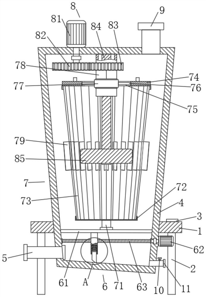
[0030] A flue gas swirling device for flue gas desulfurization, comprising a fixed plate 1, the four corners of the bottom of the fixed plate 1 are fixedly connected with supporting feet 2, and the supporting feet 2 are used to facilitate better stable support of the equipment; One end of the top of the fixed plate 1 is fixedly equipped with a control panel 3, and the top of the fixed plate 1 is fixedly connected with a swirl box 4, and the bottom of the swirl box 4 extends to the bottom of the fixed plate 1, and the swirl box 4 One side of the bottom and below the fixed plate 1 are fixedly connected with an air inlet pipe 5, which facilitates better air intake through the air inlet pipe 5; , through the exhaust pipe 9 to facilitate better exhaust; the bottom of the inner wall of the swirl box 4 is provided with a dust removal mechanism 6, and the inside of the swirl box 4 and above the dust removal mechanism 6 is provided with a swirl mechanism 7 , the top of the inner wall o...


PUM


Abstract

The invention discloses a flue gas rotational flow device for flue gas desulfurization and a use method thereof. The flue gas rotational flow device comprises a fixing plate, supporting legs are fixedly connected to the four corners of the bottom of the fixing plate, a control panel is fixedly installed at one end of the top of the fixing plate, and a rotational flow box is fixedly connected to the top of the fixing plate, and the bottom of the rotational flow box extends to the bottom of the fixing plate. The flue gas rotational flow device is compact in structure, simple and convenient to operate and high in practicability, a plurality of rotational flow blades are arranged in the rotational flow box and matched with a driving ash removal mechanism, flue gas passing through the interior of the rotational flow box can be fully subjected to rotational flow operation, then the flue gas is subjected to demisting operation, and meanwhile, a dust removal mechanism and the ash removal mechanism are arranged to be matched with each other, dust removal operation can be rapidly conducted on the rotary knob blades and the interior of the rotational flow box, therefore the cleanliness of the surfaces of the rotational flow blades is guaranteed, the rotational flow effect is greatly improved, and actual use is facilitated.

Description

technical field [0001] The invention belongs to the field of swirl devices, in particular to a flue gas swirl device for flue gas desulfurization and a method for using the same. Background technique [0002] In existing life, coking is a process in which raw coal is used as raw material and coke products are obtained by dry distillation in a high-temperature environment in a coke oven. When the main product coke is obtained, it will also be accompanied by SO 2 production and emissions. Reduce SO 2 Pollution has become the top priority of today's atmospheric environment governance, so the coke oven flue will be equipped with a desulfurization tower as the tail gas absorption and treatment device. Spray scrubbers are the most widely used. As one of the components of the countercurrent spray desulfurization tower, the design and selection of the demister play a very important role in the stable operation of the desulfurization tower. The flue gas absorbed and treated by the...

Claims


Application Information

Patent Timeline
Patent Type & Authority Applications(China)
IPC IPC(8): B01D45/14B01D45/18B08B9/087B01D53/78B01D53/50
CPCB01D45/14B01D45/18B08B9/087B01D2258/0283B01D53/78B01D53/501
Inventor 蒋佩之王建超向荣刘宁徐庆肖波
Owner 成都展望能源机械有限公司
Why Eureka
Try Eureka