
Honeycomb type heater

A technology of honeycomb heaters and heaters, applied in water heaters, fluid heaters, lighting and heating equipment, etc., can solve problems such as reduced service life, easy scaling of inner tanks, and insufficient heat transfer, and achieve the goal of using Long service life, no temperature leakage, and smooth hole wall

Pending Publication Date: 2017-02-15
王艺博
View PDF5 Cites 0 Cited by
  • Summary
  • Abstract
  • Description
  • Claims
  • Application Information

AI Technical Summary

Problems solved by technology

[0003] Aiming at the problem that although the traditional heater can meet its use requirements, the heat transfer is not fast enough, the inner tank is prone to scale, resulting in uneven heating and reducing the service life, a honeycomb heater is designed.

Method used


Image

  • Honeycomb type heater
  • Honeycomb type heater

Examples


Embodiment 1

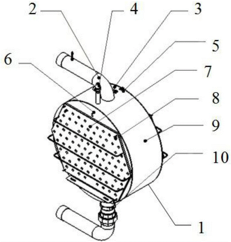
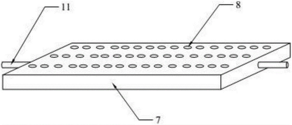
[0016] Example 1, such as figure 1 , 2 , shows: a honeycomb heater, its structure includes: heater body 1, water inlet pipe 2, over-temperature switch 3, safety valve 4, over-temperature sensor 5, temperature sensor 6, honeycomb panel 7, crystal radiation heating element 8. Aluminum silicate thermal insulation cotton 9, outlet pipe 10, connecting pipe 11; the heater body 1 is a hollow ring structure, and a water inlet pipe 2 is connected directly above the outer rotating surface of the heater body 1. A circular hole, a circular hole communicating with the water outlet pipe 10 is provided directly below the outer turning surface of the heater body 1, and the overtemperature switch 3 is arranged on the rear side of the heater body 1 provided with the water inlet pipe 2, The safety valve 4 is arranged on the front side of the heater body 1 provided with the water inlet pipe 2, the overtemperature sensor 5 is arranged on the adjacent side of the overtemperature switch 3, and the ...

Embodiment 2

[0018] Example 2, such as figure 1 , 2 , shows: a honeycomb heater, its structure includes: heater body 1, water inlet pipe 2, over-temperature switch 3, safety valve 4, over-temperature sensor 5, temperature sensor 6, honeycomb panel 7, crystal radiation heating element 8. Aluminum silicate thermal insulation cotton 9, outlet pipe 10, connecting pipe 11; the heater body 1 is a hollow ring structure, and a water inlet pipe 2 is connected directly above the outer rotating surface of the heater body 1. A circular hole, a circular hole communicating with the water outlet pipe 10 is provided directly below the outer turning surface of the heater body 1, and the overtemperature switch 3 is arranged on the rear side of the heater body 1 provided with the water inlet pipe 2, The safety valve 4 is arranged on the front side of the heater body 1 provided with the water inlet pipe 2, the overtemperature sensor 5 is arranged on the adjacent side of the overtemperature switch 3, and the ...


PUM


Abstract

The invention provides a honeycomb type heater which comprises a heater body, a water inlet pipe, an overtemperature switch, a safety valve, an overtemperature sensor, a temperature sensor, honeycomb boards, crystal radiation heating elements, aluminum silicate heat preservation cotton, a water outlet pipe and connecting pipes. The heater body is of a hollow annular structure, a round hole connected with the water inlet pipe is formed in the top of the outer rotating face of the heater body, and a round hole communicating with the water outlet pipe is formed in the bottom of the outer rotating face of the heater body. Each honeycomb board is of a rectangular structure, and the connecting pipes are arranged at the two ends of each honeycomb board. The crystal radiation heating elements are evenly distributed on each honeycomb board, and the outer rotating face of the heater body is wrapped with the aluminum silicate heat preservation cotton. The honeycomb type heater is novel, unique, uniform in heating and stable in work; heat is not dissipated, electric energy is saved, and work is safe; the honeycomb type heater has the characteristics of stable high temperature and the like, and can work at 600-800 DEG C for a long time; and a liner is made from SUS304 white steel, so that the application environment is guaranteed for clients.

Description

technical field [0001] The invention relates to a honeycomb heater and belongs to the field of heaters. Background technique [0002] The core of the heater principle is energy conversion, the most common is the conversion of electrical energy into heat energy. For example, an electric heater uses metal to generate eddy current in an alternating magnetic field to make itself heat and absorb, and converts electrical energy into light energy; such as a solar water heater, which absorbs solar radiation heat energy and converts sunlight light energy (photoelectric effect) into heat energy. Both; Bioenergy is a kind of energy that stores solar energy in the form of chemical energy with organisms as the carrier, and it comes directly or indirectly from the photosynthesis of plants. In addition, there are energy conversion modes such as nuclear energy and wind energy, but they generally need to be converted into electric energy for use. Although traditional heaters can meet their ...

Claims


Application Information

Patent Timeline
IPC IPC(8): F24H1/00F24H9/18
CPCF24H1/0018F24H9/1818
Inventor 王艺博
Owner 王艺博
Learn More