Contour scanning measurement device and method for large-aperture high-curvature optical element based on confocal microscopy

A technology of confocal microscopy and optical components, which is applied in the direction of measuring devices, optical devices, instruments, etc., can solve the problems of difficult detection, slow measurement speed, large error, etc., and achieve the effect of cost reduction and high measurement accuracy

Inactive Publication Date: 2017-02-15
HARBIN INST OF TECH
View PDF9 Cites 11 Cited by
  • Summary
  • Abstract
  • Description
  • Claims
  • Application Information

AI Technical Summary

Problems solved by technology

[0003] The purpose of the present invention is to solve the problems of the existing methods for measuring large-diameter and high-curvature optical elements that are difficult to detect, slow in measurement speed, and large in error, so as to provide a contour scanning measurement device for large-diameter and high-curvature optical elements based on confocal microscopy technology and method

Method used


Image

  • Contour scanning measurement device and method for large-aperture high-curvature optical element based on confocal microscopy
  • Contour scanning measurement device and method for large-aperture high-curvature optical element based on confocal microscopy

Examples


specific Embodiment approach 1

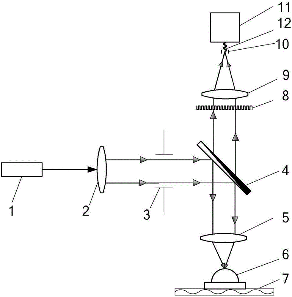
[0026] Specific implementation mode one: combine figure 1 Specifically explain this embodiment, the profile scanning measurement device based on confocal microscopy technology of large aperture and high curvature optical elements described in this embodiment includes a confocal microscopy system and a two-dimensional air-floating motion platform 7;

[0027] The confocal microscope system includes an illumination system and a detection system;

[0028] The illumination system comprises a laser 1, a collimating mirror 2, an aperture 3, a dichroic mirror 4 and an objective lens 5;

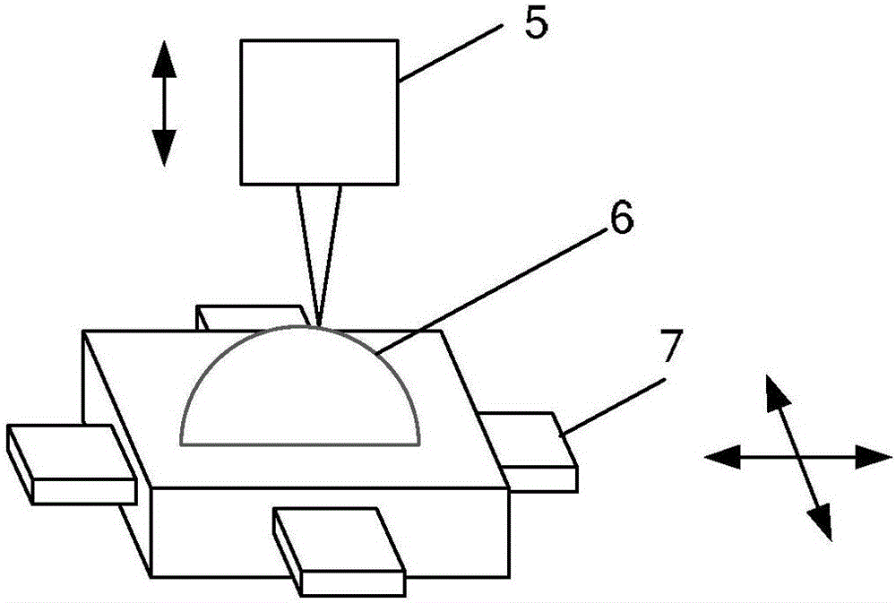
[0029] The laser light emitted by the laser 1 passes through the collimating mirror 2 to form parallel light, and the parallel light enters the dichroic mirror 4 through the aperture 3, and the dichroic mirror 4 reflects the laser light to the The objective lens 5 focuses the laser light onto the sample to be tested 6, and the sample to be tested 6 is placed on the two-dimensional air-floating motion...

specific Embodiment approach 2

[0035] Specific embodiment 2: This embodiment is a further description of the profile scanning measurement device based on confocal microscopy technology for large-aperture and high-curvature optical elements described in specific embodiment 1. In this embodiment, the laser light emitted by the laser 1 The wavelength is 532nm.

specific Embodiment approach 3

[0036] Specific embodiment three: this embodiment is a further description of the profile scanning measurement device based on the confocal microscopy technology of the large-aperture high-curvature optical element described in the specific embodiment one or two. In this embodiment, the object lens 5 transmits The laser power is greater than 0mW and less than 50mW.

[0037] The laser power incident on the sample 7 to be tested is less than 50 mW, which ensures that the surface of the sample 7 to be tested can excite fluorescence without damaging the sample to be tested.


PUM


Abstract

The invention relates to the technical field of optical precision measurement and provides a contour scanning measurement device and method for a large-aperture high-curvature optical element based on confocal microscopy, so as to solve the problems of high difficult, low measurement speed and big error of existing large-aperture high-curvature optical element measurement methods. Laser light emitted by a laser passes through a collimator, a diaphragm, a dichroic mirror and an objective lens in order, then the objective lens focuses the laser light to a to-be-measured sample, and fluorescent light excited from the surface of the to-be-measured sample passes through the objective lens, the dichroic mirror, a filter converter, a converging lens and a pinhole in order and finally goes to a photoelectric detector. The present invention is applicable to measuring large-aperture high-curvature optical elements and microstructure optical elements.

Description

technical field [0001] The invention relates to the technical field of optical precision measurement, in particular to a technology for measuring the surface profile of a large-diameter high-curvature optical element by using confocal microscopy technology. Background technique [0002] With the continuous development of optical processing and detection technology, large-aperture optical components have become one of the key components that play a supporting role in the fields of astronomical optics, space optics, and ground-based space target detection and recognition, laser atmospheric transmission, and inertial confinement fusion (ICF). First, it is also the product of the close combination of optical system design and ultra-precision processing technology. Combining the characteristics of the above fields, large-aperture optical elements can not only effectively correct advanced aberrations in the optical system, significantly improve the imaging quality of the optical s...

Claims


Application Information

Patent Timeline
Patent Type & Authority Applications(China)
IPC IPC(8): G01B11/24
CPCG01B11/24
Inventor 刘俭王宇航谷康牛斌谭久彬
Owner HARBIN INST OF TECH
Why Eureka
Try Eureka