
Large-view-field large-relative-aperture solar blind ultraviolet optical system

A technology of relative aperture and optical system, used in optics, optical components, instruments, etc., can solve the problems of poor physical and chemical properties of materials, loss of energy, difficult to correct aberrations, etc. sexual effect

Active Publication Date: 2017-02-15
LUOYANG INST OF ELECTRO OPTICAL EQUIP OF AVIC
View PDF7 Cites 20 Cited by
  • Summary
  • Abstract
  • Description
  • Claims
  • Application Information

AI Technical Summary

Problems solved by technology

[0003] In the sun-blind band, the ultraviolet optical design is divided into refraction and reflection, among which the reflection loses energy due to central occlusion, which is not good for the detection of weak ultraviolet signals
The materials of the refractive optical system are mainly ultraviolet-transparent optical crystal materials, but most of the materials have poor physical and chemical properties and are not suitable for making lenses
Considering the physical and chemical properties, radiation resistance and processing performance of materials, only two or three materials can be used in the design, such as calcium fluoride, quartz and magnesium fluoride, etc., which is difficult to correct aberrations
In addition, the ultraviolet detection system belongs to the field of weak light detection, which requires high filter transmittance, large relative aperture and high uniformity of illumination on the image plane, which further increases the difficulty of optical system design

Method used


Image

  • Large-view-field large-relative-aperture solar blind ultraviolet optical system
  • Large-view-field large-relative-aperture solar blind ultraviolet optical system
  • Large-view-field large-relative-aperture solar blind ultraviolet optical system

Examples


Embodiment Construction

[0021] The embodiments of the present invention will be described in detail below, and the examples of the embodiments are exemplary and intended to explain the present invention, but should not be construed as limiting the present invention.

[0022] In addition, the terms "first" and "second" are used for descriptive purposes only, and cannot be interpreted as indicating or implying relative importance or implicitly specifying the quantity of indicated technical features. Therefore, a feature defined as "first" or "second" may explicitly or implicitly include one or more of these features. In the description of the present invention, "plurality" means two or more, unless otherwise specifically defined.

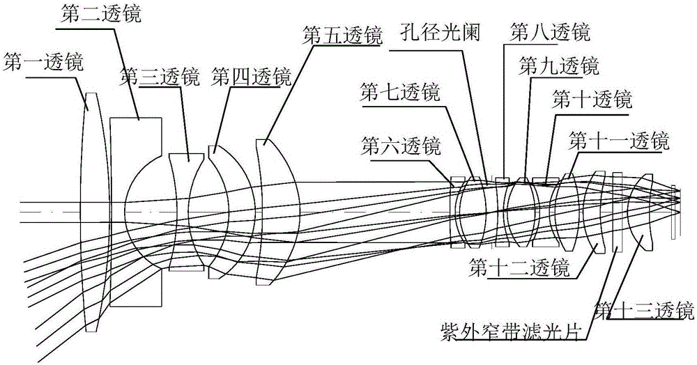
[0023] The object of the present invention is a solar-blind ultraviolet optical system with large field of view and large relative aperture, which is achieved by selecting a transmissive method that is easy to assemble and has no central occlusion, and adopts a complex negat...


PUM

PropertyMeasurementUnit
Radiusaaaaaaaaaa
Radiusaaaaaaaaaa
Surface radiusaaaaaaaaaa

Abstract

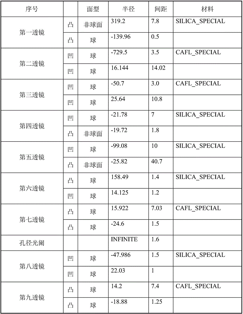
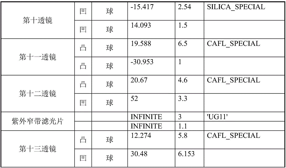
The invention discloses a large-view-field large-relative-aperture solar blind ultraviolet optical system. The system is formed by combining thirteen lenses and one ultraviolet narrowband optical filter and is sequentially composed of the first lens with positive focal power, the second lens with negative focal power, the third lens with negative focal power, the fourth lens with positive focal power, the fifth lens with positive focal power, the sixth lens with negative focal power, the seventh lens with positive focal power, an aperture diaphragm, the eighth lens with negative focal power, the ninth lens with positive focal power, the tenth lens with negative focal power, the eleventh focal power with positive focal power, the twelfth lens with positive focal power, the ultraviolet narrowband optical filter, the thirteenth lens with positive focal power and a focal plane detector from an object side to an image side. The work waveband is 260-280nm, F / # is 1.5, the focal length is 7.99mm, the view field is 75.2 degrees, and the length of the whole optical system is 157mm. The optical system realizes high illumination uniformity which is higher than 81.6%, improves the image quality by use of three aspheric surfaces and enables the total optical path lens of the optical system to be shorter. Through overall system movement, the system maintains high-quality imaging within a temperature scope from -40 DEG C to 60 DEG C.

Description

technical field [0001] The invention relates to the technical field of optical system design, in particular to a sun-blind ultraviolet optical system with large field of view and large relative aperture. Background technique [0002] Ultraviolet sensing imaging system is mainly used for biomedical analysis, ozone monitoring, offshore oil monitoring, solar illuminance monitoring, corona discharge detection, criminal investigation, forest fire prevention, space observation, diseased grain removal, mercury lamp disinfection control and disaster weather monitoring and forecasting Wait. When sunlight penetrates the earth's atmosphere, the radiation in the 220-280nm ultraviolet band is strongly absorbed by the ozone layer in the atmosphere. The transparent area of ​​the ultraviolet ordinary optical glass near the surface is generally between 350-2400nm, and the radiation is very weak. There is a so-called "Solar Spectral Blind Zone". When detecting ultraviolet targets in this ba...

Claims


Application Information

Patent Timeline
IPC IPC(8): G02B13/00G02B13/06G02B13/14G02B13/18
CPCG02B13/0045G02B13/06G02B13/143G02B13/18
Inventor 赵菲菲张良万敏潘晓东
Owner LUOYANG INST OF ELECTRO OPTICAL EQUIP OF AVIC
Learn More