Multi-path unequally-divided radial waveguide power divider

A technology of power divider and radial waveguide, which is applied in the direction of waveguide devices, circuits, electrical components, etc., can solve the problems that it is not easy to realize odd-numbered power distribution, and the volume of multi-channel distribution network is large, so as to achieve the number of power divisions The effect of flexibility, low loss, and large power capacity

Inactive Publication Date: 2017-02-15
SOUTHWEST INST OF APPLIED MAGNETICS
View PDF7 Cites 0 Cited by
  • Summary
  • Abstract
  • Description
  • Claims
  • Application Information

AI Technical Summary

Problems solved by technology

[0005] 1. Since the Wilkinson power distribution network uses microstrip lines or striplines as the carrying transmission lines of the circuit, when devices are required to achieve large-scale unequal divisions, the impedance of one branch transmission line needs to be designed to be very high, but it is limited by processing Influenced by various factors such as technology and reliability, it is not easy for this type of circuit to achieve a unequal ratio of 3:1, and there is still a considerable gap compared with the technical requirements of the amplitude-weighted antenna array.
[0006] 2. For traditional waveguide-type T-junction power dividers, multi-channel distribution needs to be realized by cascading, resulting in too large a multi-channel distribution network
And this kind of structure is not easy to realize the power distribution of odd channels

Method used


Image

  • Multi-path unequally-divided radial waveguide power divider
  • Multi-path unequally-divided radial waveguide power divider
  • Multi-path unequally-divided radial waveguide power divider

Examples


Embodiment 1

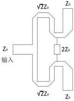
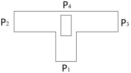
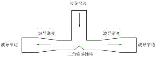
[0025] Embodiment 1: see Figure 1 to Figure 8 ,in Figure 1 to Figure 3 It is a structural diagram of three power dividers in the prior art, Figure 4-Figure 8 It is a related diagram of the present invention.

[0026] Design a multi-channel unequal radial waveguide power divider, including a hollow waveguide disk 1, the midpoint of one side of the waveguide disk 1 is provided with an input end ladder impedance converter 2, and the other side includes several waveguide The concentric ring-shaped area of ​​the disk 1, several output-end ladder impedance converters 3 are evenly distributed on each ring-shaped area,

[0027] The input-end ladder impedance converter 2 and the output-end ladder impedance converter 3 are both perpendicular to the surface of the waveguide disc 1, and are composed of a converter body and a probe 4, and the converter body is located inside the waveguide disc 1. The probe 4 passes through the surface of the corresponding waveguide disk 1;

[0028] ...


PUM


Abstract

The invention discloses a multi-path unequally-divided radial waveguide power divider. The multi-path unequally-divided radial waveguide power divider comprises a hollow waveguide circular disc, wherein an input end stepped impedance transformer is arranged on a middle point on one surface of the waveguide circular disc while a plurality of annular regions, concentric with the waveguide circular disc, are on the other surface of the waveguide circular disc; a plurality of output end stepped impedance transformers are uniformly distributed on each annular region; the input end stepped impedance transformer is connected with coaxial line feed input which generates an electric field and a magnetic field; and the electric field is parallel to the axial line of the waveguide circular disc while the magnetic field direction rotates around a circumferential direction. Based on the coaxial symmetry characteristic of the radial waveguide main mode field distribution, power division of different proportions is realized on circles with different radiuses r by taking the input port as the center, through corresponding output ports; in addition, the number of the power division paths is flexible, and multi-path and multi-proportion division can be realized; and therefore, the multi-path unequally-divided radial waveguide power divider can be widely applied to various radar systems and communication systems with amplitude modulation requirements on an antenna array.

Description

technical field [0001] The invention relates to a power splitter, in particular to a multi-channel unequal radial waveguide power divider. Background technique [0002] Power divider is an important basic device in microwave engineering. It is widely used in various civil and military equipment such as civil communication, microwave measurement, radar, communication, electronic countermeasures, and aerospace. It mainly plays a role in the equipment. The microwave energy on the transmission path can be accurately distributed to the antenna end according to the system requirements. Cooperating with the power combiner and microwave amplifier, it can play the role of amplifying small signals and synthesizing high-power microwave signals, which is indispensable in the system. key components. [0003] The traditional power divider is mainly a binary power divider, which is obtained by cascading a 2-way power divider through a binary tree structure. For example, the Wilkinson pow...

Claims


Application Information

Patent Timeline
Patent Type & Authority Applications(China)
IPC IPC(8): H01P5/16
CPCH01P5/16
Inventor 闫欢胡艺缤
Owner SOUTHWEST INST OF APPLIED MAGNETICS
Why Eureka
Try Eureka