Power supply port protective circuit

A power port protection and circuit protection technology, applied in emergency protection circuit devices, circuit devices, emergency protection circuit devices for limiting overcurrent/overvoltage, etc. Port reverse connection, overvoltage, undervoltage, overcurrent and other problems can improve the reliability of system operation, avoid reverse connection, and avoid power damage.

Active Publication Date: 2017-02-15
CRSC RESEARCH & DESIGN INSTITUTE GROUP CO LTD +1
View PDF6 Cites 5 Cited by
  • Summary
  • Abstract
  • Description
  • Claims
  • Application Information

AI Technical Summary

Problems solved by technology

[0003] At present, in the field of industrial equipment, due to reasons such as on-site operation, maintenance and complex electromagnetic environment, reverse connection, overvoltage, undervoltage, overcurrent, etc. often occur at the DC power port of the equipment, which leads to damage to the system power supply and affects subsequent circuits. Reduce system reliability

Method used


Image

  • Power supply port protective circuit
  • Power supply port protective circuit
  • Power supply port protective circuit

Examples


Embodiment 1

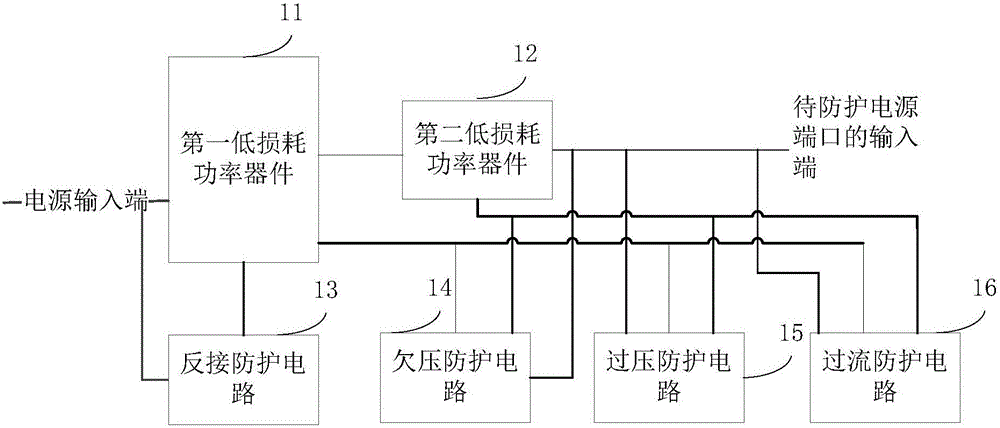
[0046] In this embodiment, a power port protection circuit is provided, please refer to figure 1 , Which shows a schematic diagram of a logical structure of the power port protection circuit provided by the present application. The power port protection circuit includes: a first low-loss power device 11, a second low-loss power device 12, a reverse connection protection circuit 13, and undervoltage Protection circuit 14, overvoltage protection circuit 15, and overcurrent protection circuit 16.

[0047] The first end of the first low-loss power device 11 is connected to the power input end, the second end of the first low-loss power device 11 is connected to the first end of the second low-loss power device 12, and the The second end of the second low-loss power device 12 is connected to the input end of the power port to be protected.

[0048] The reverse connection protection circuit 13 is respectively connected to the third terminal of the first low-loss power device 11 and the p...

Embodiment 2

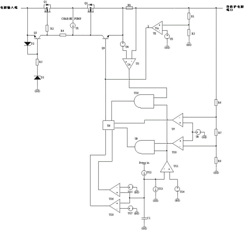
[0061] In this embodiment, it shows figure 1 Please refer to the specific electrical structure of the power port protection circuit shown figure 2 .

[0062] In this embodiment, the first low-loss power device 11 is specifically a first MOSFET (Metal-Oxide-Semiconductor Field-Effect Transistor) Q1. The second low-loss power device 12 is specifically a second MOSFET Q2.

[0063] In this embodiment, the reverse connection protection circuit 13 includes: a second diode D2, a third diode D3, a first transistor Q3, a second resistor R2, a fourth resistor R4, a fifth resistor R5, and a charge Pump U1.

[0064] The anode of the second diode D2 is connected to the power input terminal, and the cathode of the second diode D2 is respectively connected to the base of the first transistor Q3 and the fifth resistor R5. Connected at one end.

[0065] The emitter of the first transistor Q3 is connected to the anode of the second diode D2, and the collector of the first transistor Q3 is connected ...

Embodiment 3

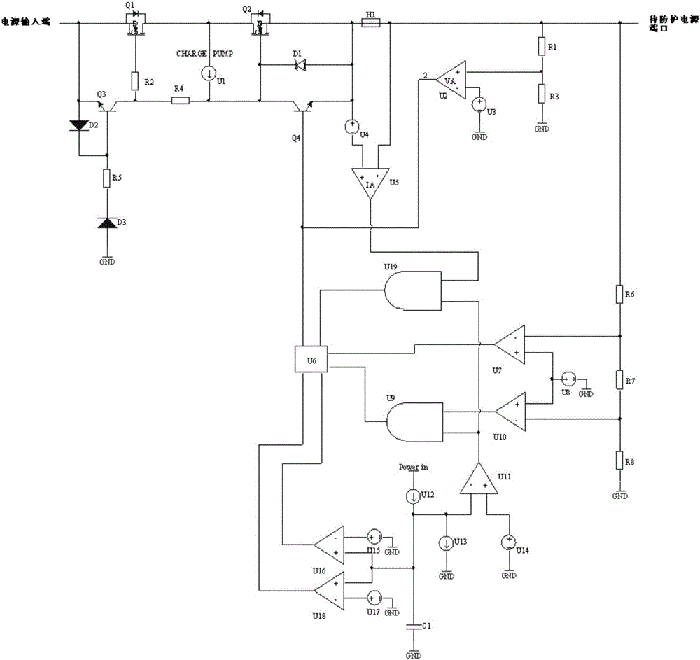
[0097] In this embodiment, in figure 2 Based on the power port protection circuit shown, another power port protection circuit is expanded, please refer to image 3 ,in figure 2 The power port protection circuit shown further includes: a first diode D1.

[0098] The anode of the first diode D1 is connected to the emitter of the second triode Q4, and the cathode of the first diode D1 is connected to the collector of the second triode Q4.

[0099] The first diode D1 is used to prevent the voltage of the second MOSFET from being too high, so as to avoid burning the second MOSFET.


PUM


Abstract

The invention provides a power supply port protective circuit. The power supply port protective circuit comprises a first low-loss power device, a second low-loss power device, a reverse-connection protective circuit, an undervoltage protective circuit, an overvoltage protective circuit and an overcurrent protective circuit, wherein the first end of the first low-loss power device is connected with a power supply input end while the second end of the first low-loss power device is connected with the first end of the second low-loss power device; the second end of the second low-loss power device is connected with the input end of a to-be-protected power supply port; the reverse-connection protective circuit is connected with the third end of the first low-loss power device and the power supply input end separately; and the undervoltage protective circuit, the overvoltage protective circuit and the overcurrent protective circuit are all connected with the second end of the first low-loss power device, the second end of the second low-loss power device and the third end of the second low-loss power device separately. By adoption of the abovementioned way, conditions of reverse connection, overvoltage, undervoltage and overcurrent and the like of the power supply port can be avoided, thereby improving operational reliability of the system.

Description

[0001] This application claims the priority of a Chinese patent application filed with the Chinese Patent Office on June 23, 2016, with an application number of 201610465106.8 and an invention title of "a power port protection circuit", the entire content of which is incorporated into this application by reference. Technical field [0002] This application relates to the field of power electronics, and in particular to a power port protection circuit. Background technique [0003] At present, in the field of industrial equipment, due to on-site operation, maintenance and complicated electromagnetic environment, the equipment DC power port often has reverse connection, overvoltage, undervoltage, overcurrent, etc., which causes damage to the system power supply and affects subsequent circuits. Reduce the reliability of system operation. [0004] It can be seen that there is an urgent need for a power port protection circuit to protect the DC power port of the device. Summary of the i...

Claims


Application Information

Patent Timeline
Patent Type & Authority Applications(China)
IPC IPC(8): H02H3/00H02H3/10H02H9/04H02H3/24
CPCH02H3/00H02H3/10H02H3/24H02H9/045
Inventor 孙超刘贞薄伟
Owner CRSC RESEARCH & DESIGN INSTITUTE GROUP CO LTD
Why Eureka
Try Eureka