LED lamp band circuit board module containing multifunctional aluminum foil, and manufacturing method

A technology of LED light strips and circuit boards, which is applied to printed circuits, printed circuits, circuit heating devices, etc., and can solve problems such as low efficiency, high cost, and short circuits

Inactive Publication Date: 2017-02-15
王定锋
View PDF5 Cites 3 Cited by
  • Summary
  • Abstract
  • Description
  • Claims
  • Application Information

AI Technical Summary

Problems solved by technology

[0002] LED light strip circuit board The circuit board of the prior art, because aluminum cannot be soldered, has not used cheap aluminum for the circuit. The conduction between them is not solder conduction, it is conducted by manually winding thin wires one by one, with high efficiency and low cost
[0003] In addition, since the LED light strip usually has a periodically set shear position, it will be cut at the shear position according to the need during use. The voltage safety regulations stipulate that the light strip circuit board has not been able to use cheap aluminum foil instead of expensive PI as the cover film to protect the back circuit, and the light strip circuit board has not been able to use aluminum foil instead of PI as the base material to make aluminum-based flexible boards with high heat dissipation. And then made into a high heat dissipation aluminum base flexible LED strip

Method used


Image

  • LED lamp band circuit board module containing multifunctional aluminum foil, and manufacturing method
  • LED lamp band circuit board module containing multifunctional aluminum foil, and manufacturing method
  • LED lamp band circuit board module containing multifunctional aluminum foil, and manufacturing method

Examples


Embodiment Construction

[0031] The present invention will be described in detail below by taking preferred embodiments as examples.

[0032] However, those skilled in the art should understand that the following descriptions are only examples and descriptions of some preferred implementations, and do not have any limitations on the claims of the present invention.

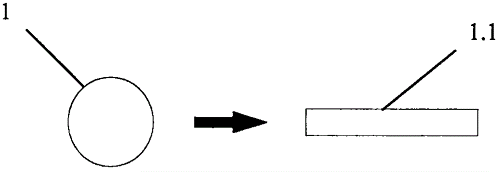
[0033] 1. The production of the top line: such as figure 1 As shown, the round copper-clad aluminum wire (1) is rolled into a flat wire with a certain width and thickness with a calender to make a back wire (1.1) whose surface is copper.

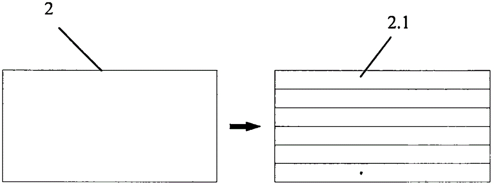
[0034] 2. Production of aluminum foil that acts as a conductive, thermally conductive, and protective layer: such as figure 2 As shown, the aluminum foil (2) is cut into strips with a slitting machine to make a plurality of aluminum foil strips (2.1) whose width is larger than that of the back line (1.1).

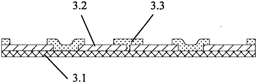
[0035] 3. Production of single-sided flexible circuit board: single-sided PCB production proce...


PUM


Abstract

The invention relates to an LED lamp band circuit board module containing a multifunctional aluminum foil, and a manufacturing method. Specifically, the back surface of a single-sided flexible circuit board is gelatinized; tin-conducting holes are punched by a die; then the positions, corresponding to the tin-conducting holes, of the back surface are covered with a metal back line, wherein an easily-tin-welded metal is at least on the surface of the metal back line; the metal back line is exposed out of the tin-conducting holes in the front surface of the single-sided flexible circuit board; the back line is covered with and packaged by multiple aluminum foil bands at certain spacings, wherein the width of the aluminum foil bands is greater than that of the back line; meanwhile, the aluminum foil bands are tightly glued by adhesive on the two sides of the back line for tightly clamping the back line in the middle to be contacted and conducted; element welding in an SMT patch manner is performed; the back line and a front surface circuit are welded together in the positions of the tin-conducting holes to enable the aluminum foil on the back surface, the metal back line, and the front surface circuit to be mutually conducted together to prepare the LED lamp band circuit board module containing the multifunctional aluminum foil. By virtue of the LED lamp band circuit board module and the manufacturing method, the problem that it is quite hard to realize connection and conduction between an aluminum circuit on the lamp band and a copper surface circuit is solved.

Description

technical field [0001] The invention relates to the application fields of circuit boards and LEDs, in particular to a circuit board module and a manufacturing method of an LED strip made of multifunctional aluminum foil. Background technique [0002] LED light strip circuit board The circuit board of the prior art, because aluminum cannot be soldered, has not used cheap aluminum for the circuit. The conduction between them is not solder conduction, but is conducted by manually winding thin wires one by one, with high efficiency and low cost. [0003] In addition, since the LED light strip usually has a periodically set shear position, it will be cut at the shear position according to the need during use. The voltage safety regulations stipulate that the light strip circuit board has not been able to use cheap aluminum foil instead of expensive PI as the cover film to protect the back circuit, and the light strip circuit board has not been able to use aluminum foil instead o...

Claims


Application Information

Patent Timeline
IPC IPC(8): H05K1/09H05K1/02
CPCH05K1/09H05K1/0201H05K2201/09218
Inventor 王定锋徐文红
Owner 王定锋
Why Eureka
Try Eureka