Endoscope light source device

A light source device and endoscope technology, applied in endoscope, medical science, surgery, etc., can solve problems such as poor optical manufacturing process, and achieve the effect of improving optical coupling efficiency

Active Publication Date: 2017-02-15
OLYMPUS CORP
View PDF5 Cites 4 Cited by
  • Summary
  • Abstract
  • Description
  • Claims
  • Application Information

AI Technical Summary

Problems solved by technology

Therefore, there is a problem that defects in optics and manufacturing process occur, and this becomes a design constraint

Method used


Image

  • Endoscope light source device
  • Endoscope light source device
  • Endoscope light source device

Examples


no. 1 approach

[0026] 〔structure〕

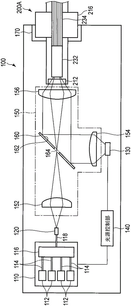
[0027] figure 1 The first embodiment of the endoscope light source device is shown.

[0028] The endoscope light source device 100 in this embodiment includes: a laser light source unit 110 that emits first light source light as a first light source unit, an LED light source unit 130 that emits second light source light as a second light source unit, and laser light source unit 110 A light source control unit 140 for controlling the LED light source unit 130, an endoscope connector 170 capable of connecting an arbitrary endoscope scope, and a first light source light emitted from the laser light source unit 110 and The light guide optical system 150 that guides the second light source light emitted from the LED light source unit 130 to the endoscope endoscope connected to the endoscope connector 170 .

[0029] The laser light source unit 110 includes a plurality of laser light sources 112 having different emission wavelengths. The plurality of laser lig...


PUM


Abstract

This endoscope light source device (100) comprises: a laser light source unit (110) that emits a laser beam; an LED light source unit (130) that emits an LED beam; and an optical path merging member (160) that merges the optical path of the laser beam and the optical path of the LED beam. The etendue of the laser light source unit (110) is smaller than the etendue of the LED light source unit (130). The optical path merging member (160) has a reflection surface (162) that reflects the LED beam, and has, in a region of the reflection surface (162), an opening (164) that lets the laser beam pass through. The optical path merging member (160) reflects the LED beam such that the central axis of the optical path of the LED beam reflected by the reflection surface (162) matches the central axis of the optical path of the laser beam that has passed through the opening (164).

Description

technical field [0001] The present invention relates to an endoscope light source device connected to an endoscope scope. Background technique [0002] In recent years, in endoscopic inspection, in addition to normal light observation using white light, special light observation using narrow-band wavelength light to improve the visibility of a living body has been performed. As a light source for generating special light, the use of laser light has drawn particular attention from the viewpoint of narrow-band characteristics, and various combinations of special light have been developed. Japanese Patent Application Laid-Open No. 2013-013560 discloses, as an example, the following structure: In order to enable the observation of the oxygen saturation of the superficial blood vessels, the optical path of the laser light is aligned with the white light through a reflection plate arranged in the optical path of the white light to reflect the laser light. The optical paths of lig...

Claims


Application Information

Patent Timeline
Patent Type & Authority Applications(China)
IPC IPC(8): A61B1/06A61B1/00
CPCA61B1/06A61B1/0661A61B1/0684A61B1/07
Inventor 田端基希伊藤毅大原聪
Owner OLYMPUS CORP
Why Eureka
Try Eureka