Medical spiral needleless transfusion joint

A helical and helical rod technology, which is applied in the field of anti-thrombotic needle-free infusion joints, can solve the problems of increasing the workload and psychological burden of medical staff, large sliding resistance of stop clip and extension tube, and the catheter assembly being pulled out of the patient's body, etc. , to achieve the effect of saving patient costs, avoiding accidental injuries, and ensuring sealing

Pending Publication Date: 2017-02-22
欧阳小青
View PDF0 Cites 1 Cited by
  • Summary
  • Abstract
  • Description
  • Claims
  • Application Information

AI Technical Summary

Problems solved by technology

This kind of operation is cumbersome and there will still be a space that cannot be filled by the sealing fluid, and negative pressure will still be generated. In order to make up for this deficiency, it is customary to put the stop clip on after clamping the extension tube. The catheter assembly slides in the direction, so that the extension tube is gradually squeezed, and the liquid in the extension tube is squeezed into the lumen of the indwelling catheter to drive out the backflow blood. However, when the stop clip and the extension tube are clamped, the sliding resistance is large. The extension tube is elongated and thinner. During the indwelling period, the catheter assembly is pulled out many times. In severe cases, the extension tube will be broken and cause bleeding. In addition, the catheter assembly is stuck on the patient's body. The length of the extension tube is limited. Inadvertently, the catheter assembly will be pulled away from the patient's body. In order to avoid the above-mentioned accidents, the medical staff should be cautious when operating. Sometimes the length of the stop clip is not enough to completely drive the blood out of the catheter. Therefore, this operation method Invisibly increase the workload and psychological burden of medical staff

Method used


Image

  • Medical spiral needleless transfusion joint
  • Medical spiral needleless transfusion joint
  • Medical spiral needleless transfusion joint

Examples


Embodiment Construction

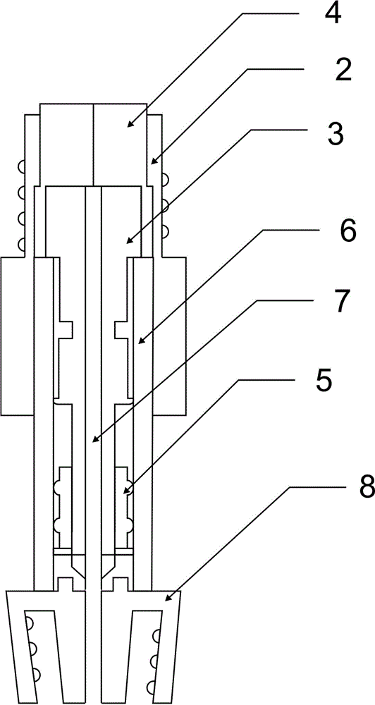
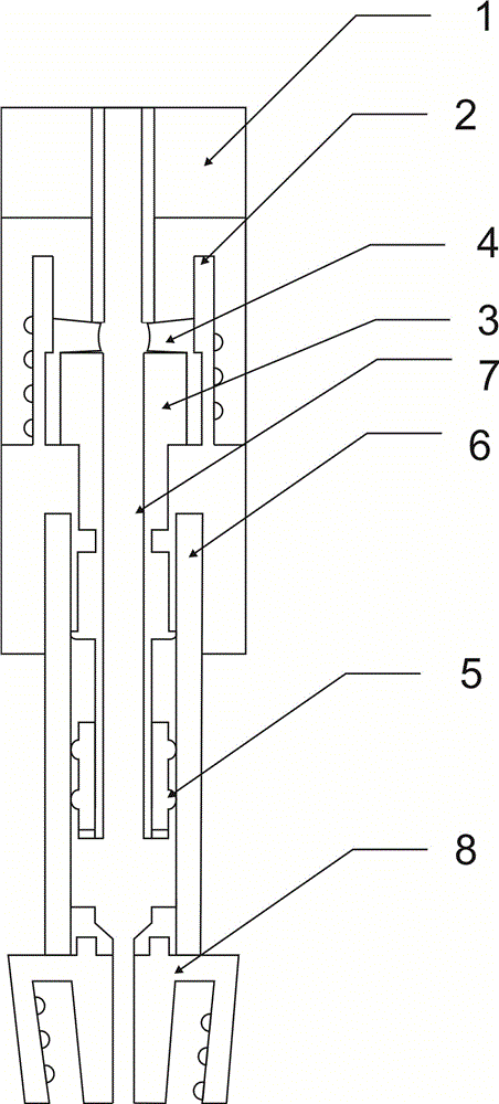
[0025] Such as figure 1 , figure 2 , image 3 and Figure 4 As shown, the present invention includes a needle-free infusion head and a needle-free infusion joint, the needle-free infusion head and the needle-free infusion joint are threadedly connected, the needle-free infusion joint is connected with a screw rod, the screw rod is placed in a spiral tube, and the spiral tube is connected to the lug The spiral tube and the needle-free infusion connector are connected through the thread on the outside of the spiral tube.

[0026] The outside of the needle-free infusion connector is threaded, and the top has an infusion through hole, which is convenient for the needle-free infusion head to be connected with the thread and is easy to fix.

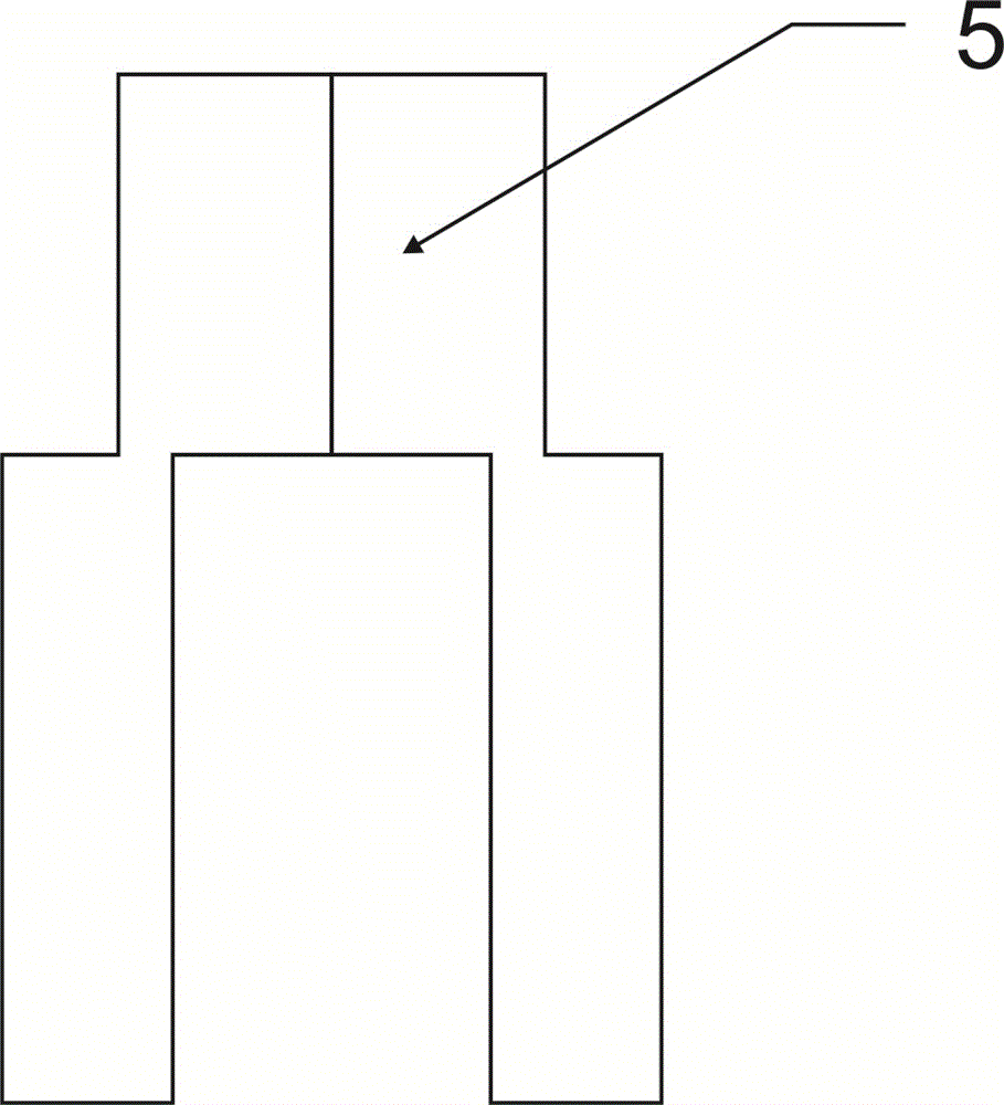
[0027] There is a closed ring at the bottom of the screw rod, and the closed ring is double ring. The closed ring structure is to ensure that the space above and below the closed ring cannot be connected when the screw rod rises or falls, s...


PUM


Abstract

A medical spiral needleless transfusion joint comprises a needleless transfusion head and a needleless transfusion joint. The needleless transfusion head is in threaded connection with the needleless transfusion joint, the needleless transfusion joint is connected with a screw rod, the screw rod is placed in a spiral pipe, the spiral pipe is connected with a Ruer taper, and the spiral pipe is connected with the needleless transfusion joint through a thread on the outer side of the spiral pipe. The medical spiral needleless transfusion joint is simple in structure and easy to operate, the needleless transfusion head is inserted from a needleless transfusion joint through hole; after sealing glues are squeezed, the two sealing glues deform, and after the two sealing glues deform, a transfusion channel is formed, so that transfusion can be performed; a seal ring is of a multi-layer seal ring structure, the sealing performance of a transfusion space in the spiral pipe is ensured, and liquid leakage is effectively avoided. During the needleless transfusion in the prior art, after transfusion is stopped, when the needleless transfusion head is twisted out, the sealing glues elastically deform and return, negative pressure is formed when the sealing glues return, and blood is pumped into a catheter. According to the medical spiral needleless transfusion joint, after the blood is pumped into the catheter, the needleless transfusion joint can be rotated to make the screw rod move forwards, the blood flowing in is pressed back to the blood vessel, and thrombosis is avoided.

Description

technical field [0001] The invention relates to medical equipment, in particular to an anti-thrombosis needle-free infusion connector for connecting with an extracorporeal catheter of an indwelling needle. Background technique [0002] In clinical medicine, when patients need multiple infusions, indwelling catheters are usually used in vitro, and the connection methods between indwelling catheters and infusion sets are divided into needle connection and needleless connection. In the prior art, there is a connection method with a needle. The medical infusion connector is composed of a connecting seat and a connector body affixed thereto. This connector body is usually also called a heparin cap. The needle tube of the infusion set is inserted through the sealing rubber plug on the top of the connector body. At the end of the infusion, when the needle tube of the infusion set is pulled out, the space occupied by the needle tube is close to a vacuum, which creates negative pres...

Claims


Application Information

Patent Timeline
Patent Type & Authority Applications(China)
IPC IPC(8): A61M5/31
CPCA61M5/31
Inventor 欧阳小青
Owner 欧阳小青
Why Eureka
Try Eureka