
Desulfurizing tower spraying, condensing, amplifying, dedusting and demisting integrated device

A desulfurization tower, spray cooling technology, applied in combined devices, chemical instruments and methods, and dispersed particle separation, etc., can solve the problems of chimney gypsum rain, unavoidable carrying a large amount of fine dust and gypsum droplets, and low removal efficiency

Inactive Publication Date: 2017-02-22
哈尔滨电气环保有限公司
View PDF7 Cites 7 Cited by
  • Summary
  • Abstract
  • Description
  • Claims
  • Application Information

AI Technical Summary

Problems solved by technology

Ultra-low emissions of flue gas pollutants from coal-fired power plants mainly involve soot, SO 2 and NO x emissions, the difficulty at this stage is how to achieve efficient dust removal
At present, the smoke and dust 5mg / Nm is achieved by using the flue gas collaborative treatment technology 3 The ultra-low emissions of ultra-low emissions are becoming more and more mainstream. The key to the success of this technology route to achieve ultra-low emissions of smoke and dust is that the wet desulfurization tower must have a strong collaborative dust removal capability. To achieve this, the concentration of smoke and dust at the inlet of the desulfurization tower must not exceed 20mg / Nm 3 , The demister in the existing desulfurization tower is based on the inertial collision theory to remove dust and mist. However, the removal efficiency of dust and gypsum droplets with a particle size below 20 μm is low, making it inevitable that a large amount of fine dust and gypsum droplets will be carried in the flue gas at the outlet of the desulfurization tower, which will easily cause chimney gypsum rain.

Method used


Image

  • Desulfurizing tower spraying, condensing, amplifying, dedusting and demisting integrated device
  • Desulfurizing tower spraying, condensing, amplifying, dedusting and demisting integrated device
  • Desulfurizing tower spraying, condensing, amplifying, dedusting and demisting integrated device

Examples


Embodiment Construction

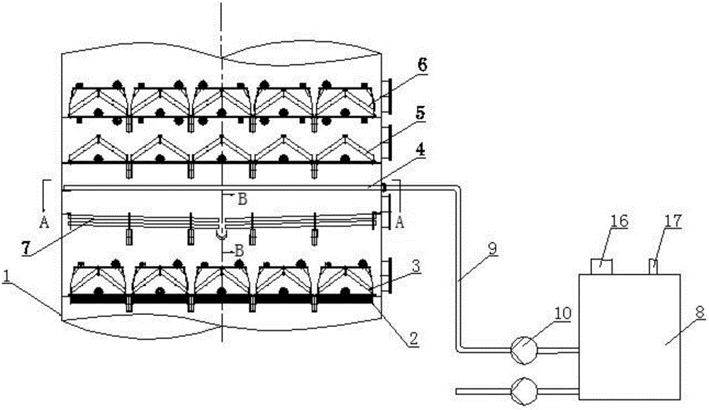
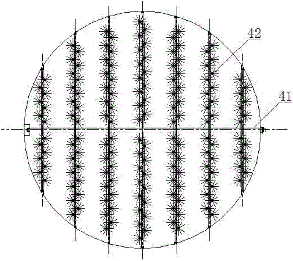
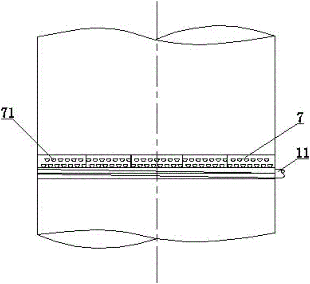
[0017] refer to figure 1 , the desulfurization tower spray condensation amplification dust removal and fog removal integrated device includes a desulfurization tower 1, a demister and a spray cooling system, and the demister is sequentially arranged from bottom to top Tubular demister 2, the first The first stage ridge type mist eliminator 3, the second stage fine ridge type mist eliminator 5 and the third stage fine ridge type mist eliminator 6, the first stage ridge type mist eliminator 3 is next to the tube type mist eliminator 2; The spray cooling system includes a cooling water spray layer 4, a liquid collector grid 7 and a cooling water tank 8, the cooling water spray layer 4 is above the liquid collector grid 7, and the liquid collector grid 7 is in the first On the top of the primary ridge type mist eliminator 3, the cooling water spray layer 4 is connected to the cooling water tank 8 through the water supply pipe 9, the water supply pump 10 is arranged on the water su...


PUM


Abstract

A desulfurizing tower spraying, condensing, amplifying, dedusting and demisting integrated device comprises a desulfurizing tower, a demister and a spray cooling system. The device is technically characterized in that the demister is composed of a tubular demister, a first-stage weir-type demister, a second-stage thin-weir-type demister and a third-stage fine-weir-type demister which are sequentially arranged from bottom to top, the spray cooling system comprises a cooling water spray layer, a liquid collection tube grid and a cooling water tank, the cooling water spray layer is arranged between the second-stage fine-weir-type demister and the first-stage weir-type demister, the liquid collection tube grid is positioned between the cooling water spray layer and the first-stage weir-type demister, the cooling water spray layer is connected with the cooling water tank through a water supply pipe, a water supply pump is arranged on the water supply pipe, the top of the liquid collection tube grid is open, and the liquid collection tube grid is connected with the cooling water tank. By the device, synergistic dedusting capacity of the desulfurizing tower can be improved effectively, system flushing water amount can be reduced, gypsum carrying amount of smoke at an outlet of the desulfurizing tower can be lowered substantially, so that gypsum rain of a chimney is eliminated thoroughly.

Description

[0001] Technical field: [0002] The invention relates to a flue gas dedusting and demisting device, in particular to an integrated device for spraying, condensing, amplifying, dedusting and defogging of a desulfurization tower. [0003] Background technique: [0004] The desulfurization process of coal-fired power plants in my country generally adopts the limestone-gypsum wet desulfurization process, and a demister is installed on the upper part of the desulfurization tower to remove fog and dust. Ultra-low emissions of flue gas pollutants from coal-fired power plants mainly involve soot, SO 2 and NO x The current difficulty is how to achieve efficient dust removal. At present, the smoke and dust 5mg / Nm is achieved by using the flue gas collaborative treatment technology 3 The ultra-low emissions of ultra-low emissions are becoming more and more mainstream. The key to the success of this technology route to achieve ultra-low emissions of smoke and dust is that the wet desul...

Claims


Application Information

Patent Timeline
IPC IPC(8): B01D50/00
CPCB01D50/40
Inventor 李珺程旺斌高晓刚
Owner 哈尔滨电气环保有限公司
Learn More