
Micro spindle for fine machining

A kind of mechanical processing and fine technology, which is applied in the direction of metal processing equipment, metal processing machinery parts, manufacturing tools, etc., can solve the problems that the speed cannot fully meet the requirements, limit the miniaturization of micro-machine tools, and complex structures, etc., to achieve the advantages of rotation accuracy, Easy to guarantee machining accuracy and good balance performance

Active Publication Date: 2017-02-22
HUNAN UNIV
View PDF6 Cites 0 Cited by
  • Summary
  • Abstract
  • Description
  • Claims
  • Application Information

AI Technical Summary

Problems solved by technology

The existing micro-spindles are divided into two types: micro-electric spindles and micro-pneumatic spindles. There are mainly three problems in the following aspects: First, the structure is complex and the volume is large. Limits the miniaturization of micro-machine tools
The inventor of this patent has designed two new ultra-high-speed precision pneumatic micro-spindles (see patents: ZL201010116981.8, ZL201310157777.4), but the volume is large and the speed cannot fully meet the requirements

Method used


Image

  • Micro spindle for fine machining
  • Micro spindle for fine machining
  • Micro spindle for fine machining

Examples


Embodiment Construction

[0026] The present invention will be described in detail below in conjunction with the embodiments and accompanying drawings.

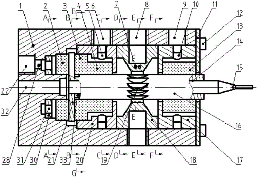
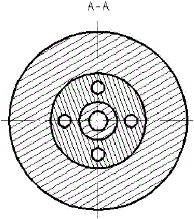
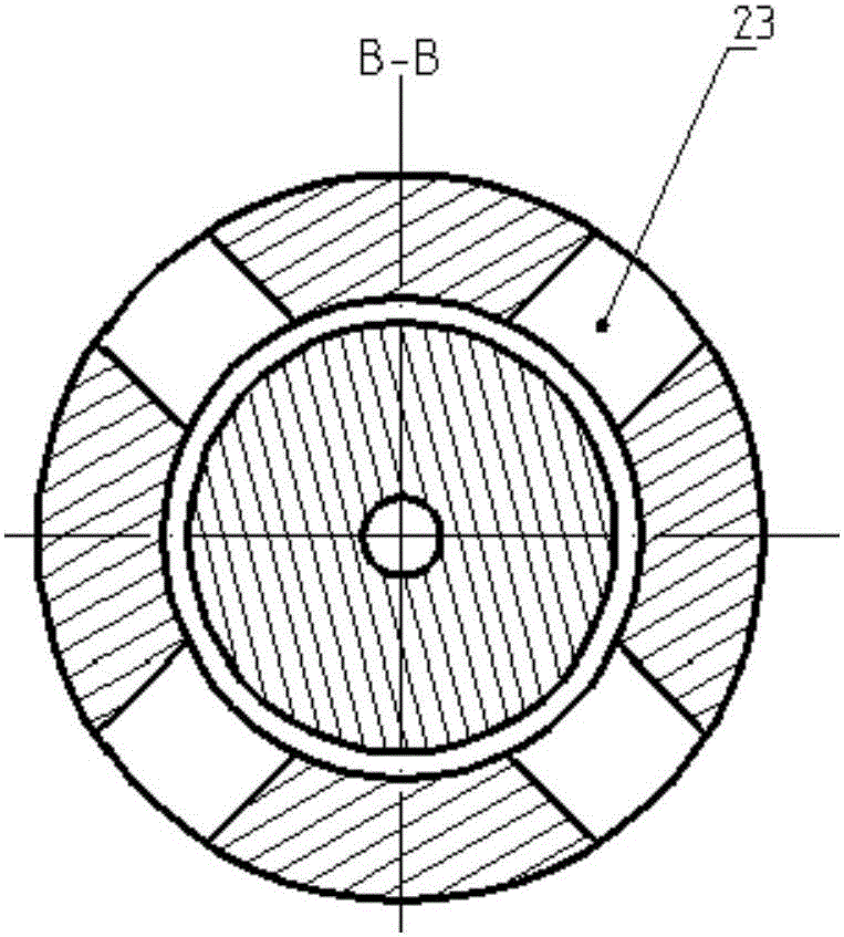
[0027] See attached figure 1 , figure 2 , image 3 , Figure 4 , Figure 5 , Image 6 , Figure 7 and Figure 8 , the turbine 19 is directly processed in the middle of the main shaft rotor 16, that is, the turbine 19 and the main shaft rotor 16 are integrated, which avoids the installation error of the turbine 16, and the blades 29 on the turbine 19 are in a regular cylindrical shape, And facing the small hole 7 on the turbine nozzle 18, the turbine nozzle 18 is provided with two circles of small holes 7 to provide high-speed air flow to drive the spindle rotor 16 to rotate at a high speed, that is, to use a pneumatic micro-turbine to realize the ultra-high-speed rotation of the micro-spindle, so The front and rear ends of the main shaft rotor 16 are radially supported by the front porous static pressure gas radial bearing 13 and the rear end ...


PUM


Abstract

The invention discloses a micro spindle for fine machining. A turbine 19 is arranged in the middle of a spindle rotor 16 and is driven by a high-speed airflow provided by a turbine nozzle 18, the spindle rotor 16 adopts a front-end porous static pressure gas radial bearing 13 and a rear-end porous static pressure gas radial bearing 14 radial support, a baffle 21 is arranged at the rear end of the spindle rotor 16, a front-end porous static pressure gas thrust bearing 3, a rear-end porous static pressure gas thrust bearing 2 axial support, a rear-end bearing supporting part 20, the turbine nozzle 18 and a front-end bearing supporting part 17 are sequentially installed in a box body 1 and are fixed through an installing plate 11, and a micro cutter 15 is clamped at the front end of the spindle rotor 16 through a thermal expansion and cold contraction effect. The micro spindle is reasonable in design, simple in structure, small in size, convenient to manufacture, high in rotating speed and small in bounce error, can serve as the micro spindle for a micro machine tool for fine machining and can be also used as the micro spindle for other high-speed high-precision micro electro mechanical devices or manual tool machines and the like.

Description

technical field [0001] The invention relates to a spindle, in particular to an ultra-high-speed precision pneumatic micro-spindle for micromachining, belonging to the field of machinery manufacturing equipment. Background technique [0002] The miniaturization of parts and the high precision of size have put forward higher and higher requirements for its processing equipment. As a key component of micro-machine tools, micro-spindle directly determines the performance of micro-machine tools and the development and application of micro-machining technologies such as micro-cutting and micro-grinding. The existing micro-spindles are divided into two types: micro-electric spindles and micro-pneumatic spindles. There are mainly three problems in the following aspects: First, the structure is complex and the volume is large. Limits the miniaturization of micro-machine tools. To meet the requirements of micro-machine tools, The length-to-diameter ratio is not greater than 3:1; ...

Claims


Application Information

Patent Timeline
IPC IPC(8): B23B19/02
CPCB23Q1/70
Inventor 李伟任莹晖周文理周志雄肖航
Owner HUNAN UNIV
Learn More