Laser die cutting device for battery core pole lugs

A laser die-cutting and lug technology, which is applied to laser welding equipment, welding/welding/cutting items, manufacturing tools, etc., can solve problems such as equipment failure, tab deformation, and bumping into grooves, so as to avoid interference , Dust removal effect is good, and the effect of ensuring cutting accuracy

Active Publication Date: 2017-02-22
WUXI LEAD INTELLIGENT EQUIP CO LTD
View PDF7 Cites 13 Cited by
  • Summary
  • Abstract
  • Description
  • Claims
  • Application Information

AI Technical Summary

Problems solved by technology

In CN102642087B, a laser cutting dust removal device is disclosed. The cutting backing plate is provided with several grooves, and the bottom of the grooves is connected with the air inlet passage and the suction passage, and the dust is sucked away by a dust suction fan; however, the laser cutting is extremely When cutting, the pole piece will have a downward deformation trend under the action of the laser and the vacuum fan. On the one hand, the laser is not easy to cut off the pole piece. On the other hand, the pole piece will touch the groove during the advancement process, resulting in extreme Deformed ears
In CN104972227A, a laser continuous cutting device with dust removal function is disclosed. A laser cutting channel and an adsorption hole are arranged on one side of the transmission roller. It will attract the pole piece, making it difficult for the pole piece to move forward
[0004] In addition, most existing laser die-cutting devices can only cut tabs on one side of the pole piece, but more and more customers require that they can cut on both sides of the pole piece at the same time, and ensure the tabs on both sides The center line is on the same straight line, and the existing equipment cannot meet this requirement

Method used


Image

  • Laser die cutting device for battery core pole lugs
  • Laser die cutting device for battery core pole lugs
  • Laser die cutting device for battery core pole lugs

Examples


Embodiment Construction

[0030] The present invention will be further described below in conjunction with specific drawings.

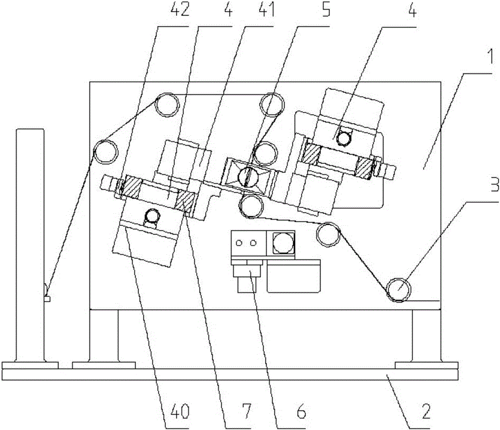
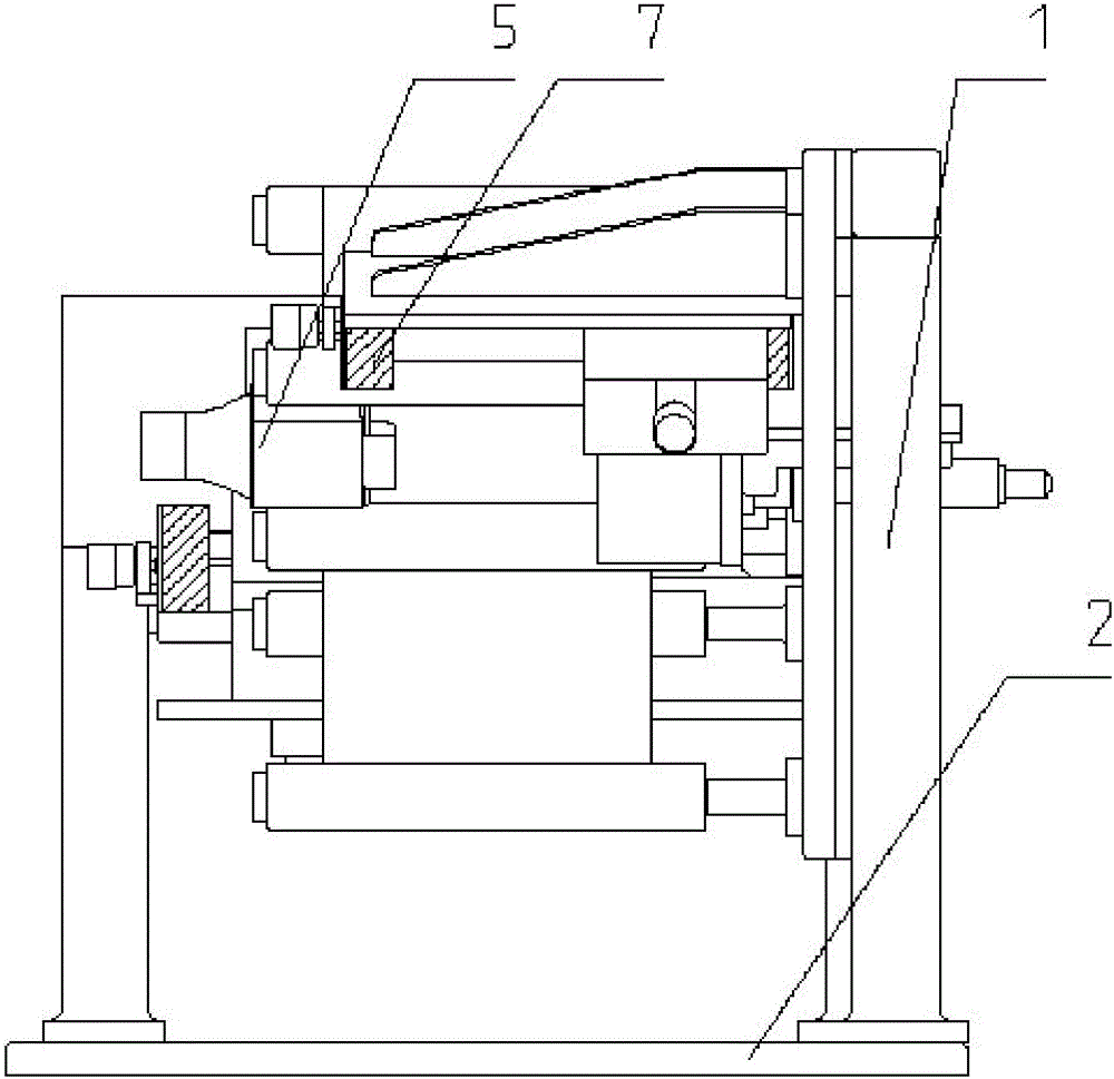
[0031] Such as Figure 2 to Figure 11 As shown: the battery tab laser die-cutting device includes a frame plate 1, a frame bottom plate 2, a roller 3, a laser die-cutting mechanism 4, a dust removal mechanism 5, a waste collection mechanism 6, a dust cover 7, a support Plate 40, laser head 41, adjustment mechanism 42, left side plate 51, right side plate 52, upper side plate 53, lower side plate 54, gap 55, laser channel 56, left air knife 57, right air knife 58, material box 61. Frequency conversion motor 62, second bottom plate 63, auxiliary roller 64, brush roller 65, pulley 66, first gear 67, second gear 68, material passage 69, first scale fine-tuning 401, line rail seat 402, the first A bottom plate 421 , an adjustment platform 422 , a second scale fine-tuning 423 , a first screw 424 , a screw nut 425 , a spacer 426 , a fixing plate 427 , a connecting plate 428 , and a ...


PUM


Abstract

The invention relates to laser die cutting device for battery core pole lugs. The laser die cutting device is characterized by comprising laser die cutting mechanisms arranged on one side or two sides of a pole piece. Each laser die cutting mechanism comprises a laser head. A dedusting mechanism is arranged, in the directions facing the pole piece, on the laser heads and comprises a dedusting shell, a gap allowing penetration of the pole piece is formed in dedusting shell, and laser paths are formed in side plates, facing the laser head, of the dedusting shell. A left air blade and a right air blade are mounted on the dedusting shell, oppositely arranged on two sides of the pole piece and used for blowing symmetrically on two sides of the pole piece to keep constant position and constant distance between the pole piece and the dedusting shell. The dedusting shell is connected with an induced draft device. The laser die cutting device for the battery core pole lugs has the advantages that by symmetrical blowing from two sides of the pole piece during cutting, a good dedusting effect is achieved, the dedusting mechanism is prevented from interfering with the pole piece, and cutting precision of the pole lugs is guaranteed.

Description

technical field [0001] The invention relates to a laser die-cutting device for battery tabs, belonging to the technical field of lithium battery manufacturing equipment. Background technique [0002] Lithium-ion battery is a battery made by winding or laminating the positive and negative electrodes into the required battery cells and injecting electrolyte and other processes. The positive and negative electrodes are composed of a current collector with a layer of coating on the upper and lower surfaces and a layer of metal in the middle. In the pole piece manufacturing process, it is necessary to use laser cutting pole pieces, such as figure 1 As shown, the sheet material of the pole piece includes the coating area D and the blank area E. The sheet material moves horizontally continuously, and the laser head cuts the sheet material according to the dotted line shown in the F position to form the tab G. [0003] The laser will generate dust during the cutting process. If th...

Claims


Application Information

Patent Timeline
Patent Type & Authority Applications(China)
IPC IPC(8): B23K26/142B23K26/38B23K26/70B23K101/36
CPCB23K26/142B23K26/38B23K26/702B23K2101/36
Inventor 陈晓飞
Owner WUXI LEAD INTELLIGENT EQUIP CO LTD
Why Eureka
Try Eureka