Fastening and connecting assembly and structure, disassembling method, track structure, crankshaft connecting rod system, bone connecting device and bone connecting method

A technology for fastening connections and components, applied in the direction of connecting components, locking fasteners, threaded fasteners, etc., which can solve the problem of the difficulty of the anti-rotation sleeve, the useless fastening of the connection components, and the inability to stop the rotation from the first Problems such as taking out of the hole

Pending Publication Date: 2017-02-22
杨东佐
View PDF12 Cites 20 Cited by
  • Summary
  • Abstract
  • Description
  • Claims
  • Application Information

AI Technical Summary

Problems solved by technology

[0013] Aiming at the problems existing in the prior art, the technical problem to be solved by the present invention is to overcome the prior recognition by those skilled in the art that the anti-rotation sleeve is used to limit the rotation of the locking nut relative to the screw rod to realize the reverse loosening of the locking nut of the bolt. The anti-loosening technical solution, because the anti-rotation sleeve is difficult or impossible to take out from the first anti-rotation hole, resulting in the inertial thinking of fastening the connection components without use value, provides a method that uses the anti-rotation sleeve to limit the rotation of the locknut relative to the screw Realize that the screw lock nut cannot rotate relative to each other, so that the screw lock nut will not be loosened due to reverse rotation, and the anti-rotation sleeve can be taken out from the first anti-rotation hole quickly, conveniently and reliably, so that the screw and lock nut can be disassembled Fast, convenient and reliable fastening connection component and structure, disassembly method, track structure, crankshaft linkage mechanism, bone connection device and bone connection method

Method used


Image

  • Fastening and connecting assembly and structure, disassembling method, track structure, crankshaft connecting rod system, bone connecting device and bone connecting method
  • Fastening and connecting assembly and structure, disassembling method, track structure, crankshaft connecting rod system, bone connecting device and bone connecting method
  • Fastening and connecting assembly and structure, disassembling method, track structure, crankshaft connecting rod system, bone connecting device and bone connecting method

Examples


Embodiment 1

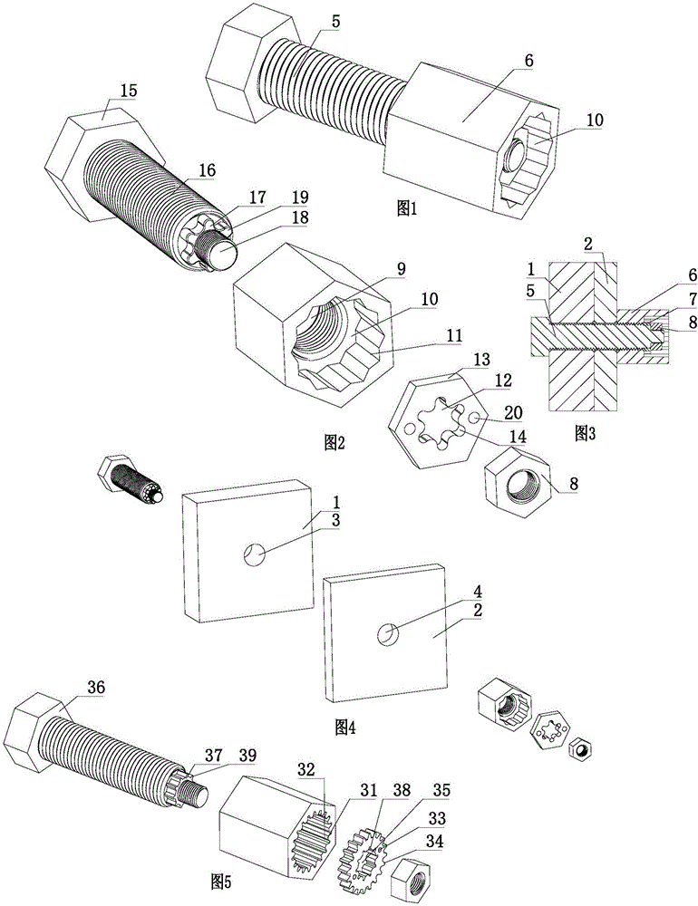
[0150] As shown in FIGS. 1 to 4 , a fastening connection structure includes a fastening connection assembly, a mother body 1 and an appendage 2 . The base body 1 is provided with a through hole 3 , and the attached body 2 is provided with a through hole 4 .

[0151] The fastening connection assembly includes a screw rod 5, a lock nut 6, an anti-rotation sleeve 7, and an anti-rotation sleeve limiter. The stopper of the anti-rotation sleeve is a blocking nut 8.

[0152] The locking nut 6 is provided with a threaded through hole 9 and a first anti-rotation hole 10 communicating with the threaded through hole 9 , and the minimum diameter of the first anti-rotation hole 10 is larger than the diameter of the threaded through hole 9 . First anti-rotation portions 11 arranged in the circumferential direction are arranged on the hole wall of the first anti-rotation hole 10 . The hole wall of the first anti-rotation hole 10 is an intersecting structure in which two regular hexagonal h...

Embodiment 2

[0160] As shown in Figure 5, different from Embodiment 1, the hole wall of the first anti-rotation hole 31 is in the shape of an internal gear, and the hole wall of the first anti-rotation hole 31 is evenly arranged with a plurality of axial trapezoidal grooves in the circumferential direction. A single trapezoidal groove forms a first anti-rotation portion 32 . The outer circumference of the anti-rotation sleeve 33 is in the shape of an external gear matching the hole wall of the first anti-rotation hole 31 , and the outer circumference of the anti-rotation sleeve 33 is evenly arranged with a plurality of axial trapezoidal teeth, and a single trapezoidal tooth forms the second anti-rotation part 34 . The anti-rotation through hole 35 of the anti-rotation sleeve 33 is an internal gear shape, and the anti-rotation shaft 37 of the screw rod 36 is an external gear shape matched with the anti-rotation through hole 35 of the internal gear shape. A plurality of axial trapezoidal gr...

Embodiment 3

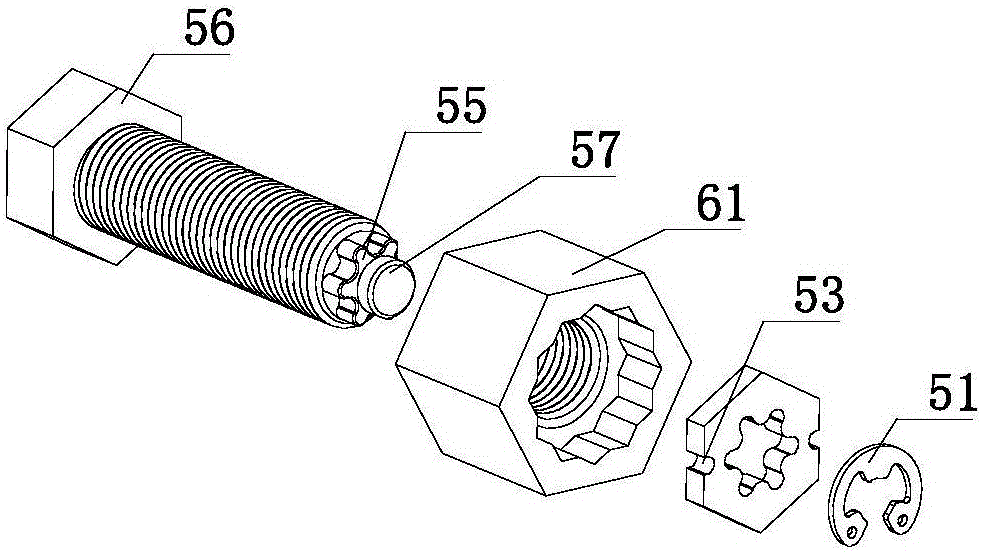
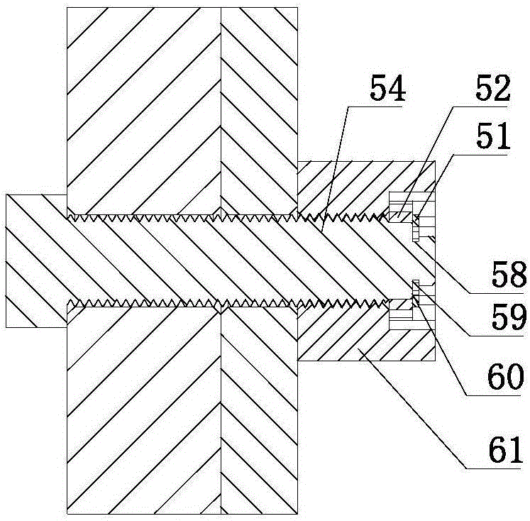
[0163] Such as Figure 6 , Figure 7 As shown, the difference from Embodiment 1 is that the stopper of the anti-rotation sleeve is a snap ring 51 . Two axial clamping recesses 53 symmetrical to the axis of the anti-rotation sleeve 52 are provided on the outer periphery of the anti-rotation sleeve 52 . A mounting portion 57 is provided on the end surface of the anti-rotation shaft 55 of the screw 54 away from the resisting portion 56 , and an annular locking groove 58 is provided on the outer periphery of the mounting portion 57 , and the locking groove 58 faces the side wall 59 of the anti-rotation shaft 55 and the anti-rotation shaft 55 The end face 60 is flush, so that when the snap ring 51 axially limits the stop sleeve 52, there is no axial gap between the stop sleeve 52, the lock nut 61, and the snap ring 51, and the stop sleeve 52 does not fit in the slot 58. It can move axially, which greatly reduces noise in places with large vibrations. The maximum outer diameter...


PUM


Abstract

The invention discloses a fastening and connecting structure. The fastening and connecting structure comprises a parent body, an affiliated body and a fastening and connecting assembly. The fastening and connecting assembly comprises a threaded rod, a locking nut and an anti-rotation sleeve. The threaded rod penetrates the parent body and the affiliated body and is in threaded connection with the locking nut. Clamping holes are formed in the anti-rotation sleeve, or clamping sunken portions communicating with the outer circumference of the anti-rotation sleeve are arranged on the outer circumference of the anti-rotation sleeve. The anti-rotation sleeve is mounted out of the threaded rod, arranged in a first anti-rotation hole and limited in the axial direction. A first anti-rotation portion on the hole wall of the first anti-rotation hole of the locking nut cooperates with a second anti-rotation portion at the outer circumference of the anti-rotation sleeve, so that the locking nut is restricted from rotating relative to the anti-rotation sleeve. A third anti-rotation portion on the hole wall of a first anti-rotation through hole of the anti-rotation sleeve cooperates with a fourth anti-rotation portion of the threaded rod, so that the anti-rotation sleeve is restricted from rotating relative to the threaded rod. The threaded rod and the locking nut are mounted together in a manner that the threaded rod and the locking nut cannot rotate. The fastening and connecting structure has the beneficial effects that the situation that the locking nut is rotated in the reverse direction relative to the threaded rod and get loosened is avoided; and the anti-rotation sleeve can be taken out of the first anti-rotation hole conveniently, rapidly and reliably.

Description

[0001] Technical field: [0002] The invention relates to a fastening connection technology for statically connecting two or more objects with threaded pairs; in particular, it relates to a method for statically connecting crankshaft linkage mechanisms, track structures, aircraft, ships, equipment, aerospace equipment, etc. through threaded pairs. Fastening connection components, fastening connection structures and connections of mechanical parts on key parts of aircraft carriers, spaceships, rockets, engines, nuclear reaction equipment, trains, high-speed rail, rails, steel structure buildings, steel structure bridges, automobiles, etc. method, disassembly method, the use environment of these mechanical parts is particularly harsh, such as large vibration, high temperature environment, heavy load, etc., and the connection reliability of the threaded mechanical static connection is particularly high. Background technique [0003] The thread pair mechanical static connection be...

Claims


Application Information

Patent Timeline
Patent Type & Authority Applications(China)
IPC IPC(8): F16B35/04F16B37/14F16B37/04F16B43/00F16B13/10F16B13/06
CPCB60B35/004B62J1/00B62K21/18B62M3/00F16B39/10F16B39/28F16B13/04F16B13/06F16B35/041F16B37/041F16B37/14F16B43/00F16B39/282F16C3/12B62K2206/00F16B13/10
Inventor 杨东佐
Owner 杨东佐
Why Eureka
Try Eureka