
Indoor air automatic ventilating system

A ventilation system and indoor air technology, applied in ventilation systems, heating and ventilation control systems, heating and ventilation safety systems, etc., can solve the problem of complex composition of final products of decomposed polluted gases, negligible chemical pollution, and aggravated air pollution and other problems, to achieve the effect of easy promotion, obvious removal effect and short removal time

Inactive Publication Date: 2017-02-22
LANZHOU UNIVERSITY
View PDF7 Cites 2 Cited by
  • Summary
  • Abstract
  • Description
  • Claims
  • Application Information

AI Technical Summary

Problems solved by technology

[0003] Air purifiers can effectively remove particulate matter in indoor air, but they have little effect on chemical pollution in the air and may even aggravate air pollution
[0004] The photocatalyst is nanoparticle TiO 2 , it can clear indoor air chemical pollution to a certain extent, but it makes a layer of nano-sized particles adhere to the indoor surface. Once it enters the air and is inhaled by the human body, it will cause serious damage to the human respiratory system. The composition of the final product of photocatalyst decomposing polluted gas is complex and has not been determined. Therefore, photocatalyst may cause secondary pollution of indoor environment
[0005] The most effective way for the indoor fresh air system to deal with indoor pollution is ventilation. The indoor fresh air system plays an important role. It can not only remove indoor air pollution, but also purify the outdoor air and send it indoors to supplement indoor fresh air. But its working principle is Replacement of air in the entire indoor space, which will result in higher energy consumption of the fresh air system

Method used


Image

  • Indoor air automatic ventilating system

Examples


Embodiment 1

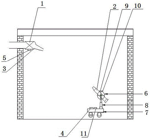
[0032] The exhaust system 1 is fixed on the outer wall, and the jet flow blower unit 2 is moving through the mobile device 7. When the air sensor 9 detects that the indoor air pollution value exceeds the set value, the value is sent to the microcomputer 4, and the microcomputer 4 sends instructions to the wireless The transmitting device 11 sends a wireless signal to the exhaust system 1 to start the exhaust fan 3 in the exhaust system 1 to run, and the infrared transmitting device 5 transmits an infrared signal.

[0033] The microcomputer 4 also sends instructions to the micromotor of the telescopic rod 8, and the jet blower unit 2 sends the jet blower 6 to the height of the polluted area through the telescopic rod 8.

[0034] The infrared receiving device 10 on the jet blower unit 2 senses the indoor infrared signal strength to realize infrared alignment, aligns the exhaust pipe of the jet blower 6 with the direction of the exhaust system 1, and the jet blower 6 sucks the pol...

Embodiment 2

[0037] The exhaust system 1 is set at the center of the ceiling of the room. During the movement of the jet flow blower unit 2 through the mobile device 7, the air sensor 9 detects that the indoor air pollution value exceeds the set value, and sends the value to the microcomputer, and the microcomputer sends an instruction to The wireless transmitting device sends a wireless signal to the exhaust system 1 to start the exhaust fan 3 in the exhaust system 1 to run, and the infrared transmitting device 5 transmits an infrared signal.

[0038] The microcomputer also sends instructions to the micromotor of the telescopic rod, and the jet blower unit 2 sends the jet blower 6 to the height of the polluted area through the telescopic rod 8.

[0039] The infrared receiving device on the jet blower unit 2 senses the indoor infrared signal strength to realize infrared alignment, and aligns the exhaust pipe of the jet blower 6 with the direction of the exhaust system 1, and the jet blower ...


PUM


Abstract

The invention discloses an indoor air automatic ventilating system which consists of an exhaust system and a jet flow air supply unit, wherein the exhaust system comprises an exhaust fan and an infrared emission device; the jet flow air supply unit comprises a micro computer, a jet flow air feeder, an infrared receiving device, a moving device, an air sensor, a telescopic rod and a wireless emission device; the exhaust system is fixed on an outer wall of a building, or an outer window, or an indoor ceiling; the jet flow air supply unit is placed in a room; and the exhaust system is wirelessly connected with the jet flow air supply unit. The indoor air automatic ventilating system can monitor an indoor air pollution index in real time and remove pollutants after determining a pollution source, and is short in clearing time and obvious in removal effect. According to the indoor air automatic ventilating system, all indoor air is not needed to be replaced, so that the air exchange amount is reduced, the indoor and outdoor heat exchange is reduced, and energy is saved.

Description

technical field [0001] The invention relates to indoor air cleaning technology and indoor ventilation technology, in particular to an automatic indoor air ventilation system, which has the function of automatically identifying the air quality at indoor pollution sources and performing local ventilation. Background technique [0002] The indoor air pollution of today's buildings is serious, especially in newly renovated rooms, where various materials and adhesives continuously emit toxic and harmful gases. At the same time, the destruction of the ecological environment has led to a continuous decline in outdoor air quality, and the concentration of particulate matter in the air has exceeded the allowable range. Therefore, the indoor air pollution control industry has developed rapidly, and various indoor air control products have emerged as the times require, which are mainly divided into three categories: air purifiers, photocatalysts, and indoor fresh air systems. [000...

Claims


Application Information

Patent Timeline
Patent Type & Authority Applications(China)
IPC IPC(8): F24F7/007F24F11/00
CPCF24F7/007F24F11/30F24F11/58F24F11/62F24F2110/50
Inventor 王厚成焦继宗
Owner LANZHOU UNIVERSITY
Learn More