Running method of heat pump unit of energy-self-supplied gas engine

An operation method and gas engine technology, applied in the direction of machine operation, energy industry, heating and refrigeration combination, etc., can solve problems such as unfavorable popularization and application of gas engine heat pumps, improve practicability and adaptability, and overcome high initial investment 、To overcome the effect of long laying period

Active Publication Date: 2017-02-22
TIANJIN CHENGJIAN UNIV
View PDF7 Cites 7 Cited by
  • Summary
  • Abstract
  • Description
  • Claims
  • Application Information

AI Technical Summary

Problems solved by technology

However, there is no good solution for the gas engine heat pump under the condition of gas supply with

Method used


Image

  • Running method of heat pump unit of energy-self-supplied gas engine
  • Running method of heat pump unit of energy-self-supplied gas engine

Examples


Example Embodiment

[0058] Example 1

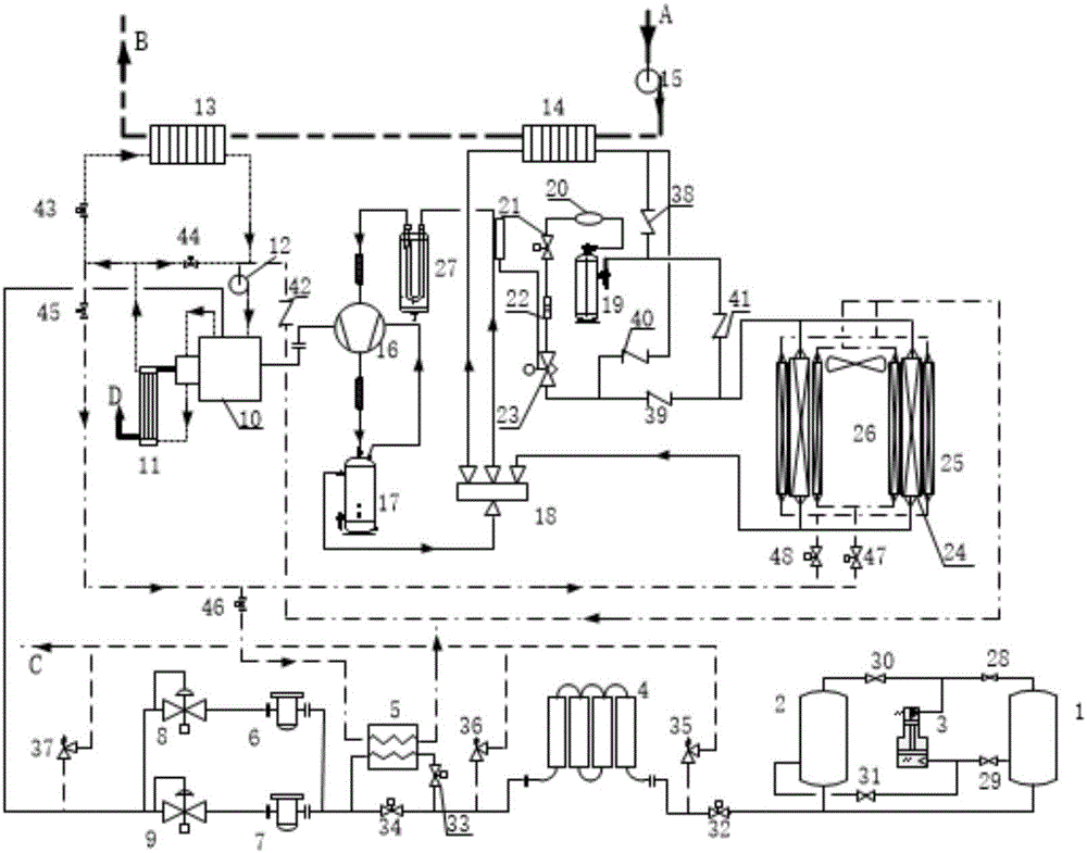
[0059] Heating mode operation:

[0060] The operation process of the heating mode includes a heating cycle, a waste heat recovery cycle and a user hot water supply cycle, and the heating cycle steps are as follows:

[0061] (a) When the internal pressure of each gas storage cylinder 1 and 2 in the liquefied natural gas (LNG) gas storage cylinder group is higher than the set pressure by 0.3MPa, the LNG directly flows out through the liquid phase port of each gas storage cylinder under the action of the pressure When the pressure in each gas storage cylinder 1 and 2 in the LNG storage cylinder group is lower than the set pressure of 0.3MPa, the self-pressurized gasifier 3 is opened, and the LNG in each gas storage cylinder 1 and 2 is opened. The gas flows out from the respective liquid phase ports of the gas storage cylinders and then flows back to the gas storage cylinders 1 and 2 through the outlet gate valve respectively, so that the pressure in the gas st...

Example Embodiment

[0070] Example 2

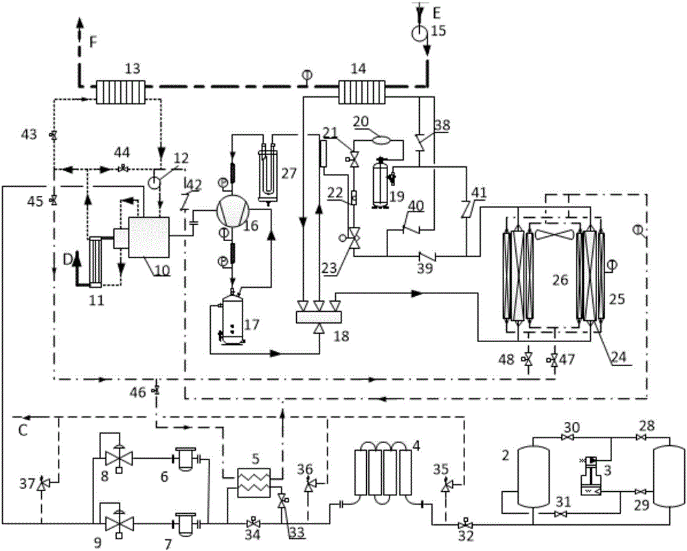
[0071] Heating mode operation:

[0072] The operation process of the heating mode includes a heating cycle, a waste heat recovery cycle and a user hot water supply cycle, and the heating cycle steps are as follows:

[0073] (a) When the internal pressure of each gas storage cylinder 1 and 2 in the liquefied natural gas (LNG) gas storage cylinder group is higher than the set pressure by 0.35MPa, the LNG directly flows out through the liquid phase port of each gas storage cylinder under the action of the pressure. ; When the pressure in each gas storage cylinder 1 and 2 in the LNG storage cylinder group is lower than the set pressure of 0.35MPa, the self-pressurized gasifier 3 is opened, and the LNG in each gas storage cylinder 1 and 2 is opened. The gas flows out from the respective liquid phase ports of the gas storage cylinders and then flows back to the gas storage cylinders 1 and 2 through the outlet gate valve respectively, so that the pressure in the g...

Example Embodiment

[0082] Example 3

[0083] Heating mode operation:

[0084] The operation process of the heating mode includes a heating cycle, a waste heat recovery cycle and a user hot water supply cycle, and the heating cycle steps are as follows:

[0085] (a) When the internal pressure of each gas storage cylinder 1 and 2 in the liquefied natural gas (LNG) gas storage cylinder group is higher than the set pressure by 0.35MPa, the LNG directly flows out through the liquid phase port of each gas storage cylinder under the action of the pressure. ; When the pressure in each gas storage cylinder 1 and 2 in the LNG storage cylinder group is lower than the set pressure of 0.35MPa, the self-pressurized gasifier 3 is opened, and the LNG in each gas storage cylinder 1 and 2 is opened. The gas flows out from the respective liquid phase ports of the gas storage cylinders and then flows back to the gas storage cylinders 1 and 2 through the outlet gate valve respectively, so that the pressure in the g...


PUM


Abstract

The invention discloses a running method of a heat pump unit of an energy-self-supplied gas engine. The running method is divided into a heating mode running process and a refrigerating mode running process. The heating mode running process comprises heating circulation, waste heat recovery and circulation and circulation of hot water supplied for a user, the refrigerating mode running process comprises a refrigerating circulation and engine heat-dissipation process of the gas heat pump unit and a process of circulation of chilled water supplied for the user. By the method, the unit can independently run for above 100 hours in regions where gas pipe networks are not paved or are not paved in time. The shortcomings that the initial cost for construction of the gas pipe networks is high, and the pavement working hours are long are overcome. Practicability and adaptability of the heat pump unit of the gas engine are improved. Meanwhile, in a gasification process of liquefied natural gas, the temperature of the hot water supplied for the user can be increased by waste heat of the gas engine, heat can further be provided for gasification of the liquefied natural gas, and stability of gas supply is guaranteed.

Description

technical field [0001] The invention relates to an operating method of a gas engine-driven heat pump, in particular to an operating method of a self-supplied energy gas engine heat pump unit. Background technique [0002] Faced with increasingly serious environmental problems such as air pollution and the greenhouse effect, China is vigorously promoting the use of clean energy such as natural gas. However, due to the vast territory of our country and the influence of objective factors such as environment, humanities, resource distribution and economic development level differences in various places, the construction of natural gas pipeline network in my country is relatively lagging behind, which has greatly hindered the development and application of natural gas in my country. Especially in the application process of gas engine heat pump technology, it is often unable to use due to lack of pipeline gas source. Chinese patents with patent application numbers CN201520907822....

Claims


Application Information

Patent Timeline
IPC IPC(8): F25B27/02F25B29/00F25B41/04F25B47/02F25B41/20
CPCF25B27/02F25B29/003F25B47/02F25B2347/02F25B2327/001F25B41/20Y02A30/274Y02P80/15
Inventor 刘凤国田中允李亚军董付江加磊磊
Owner TIANJIN CHENGJIAN UNIV
Why Eureka
Try Eureka