Natural gas liquefaction
a natural gas and liquefaction technology, applied in the direction of refrigeration and liquidation, solidification, lighting and heating equipment, etc., can solve the problems of no pipeline infrastructure that would allow for convenient transportation, and little attention has been given to the efficiency of the hydrocarbon removal step
- Summary
- Abstract
- Description
- Claims
- Application Information
AI Technical Summary
Benefits of technology
Problems solved by technology
Method used
Image
Examples
example 1
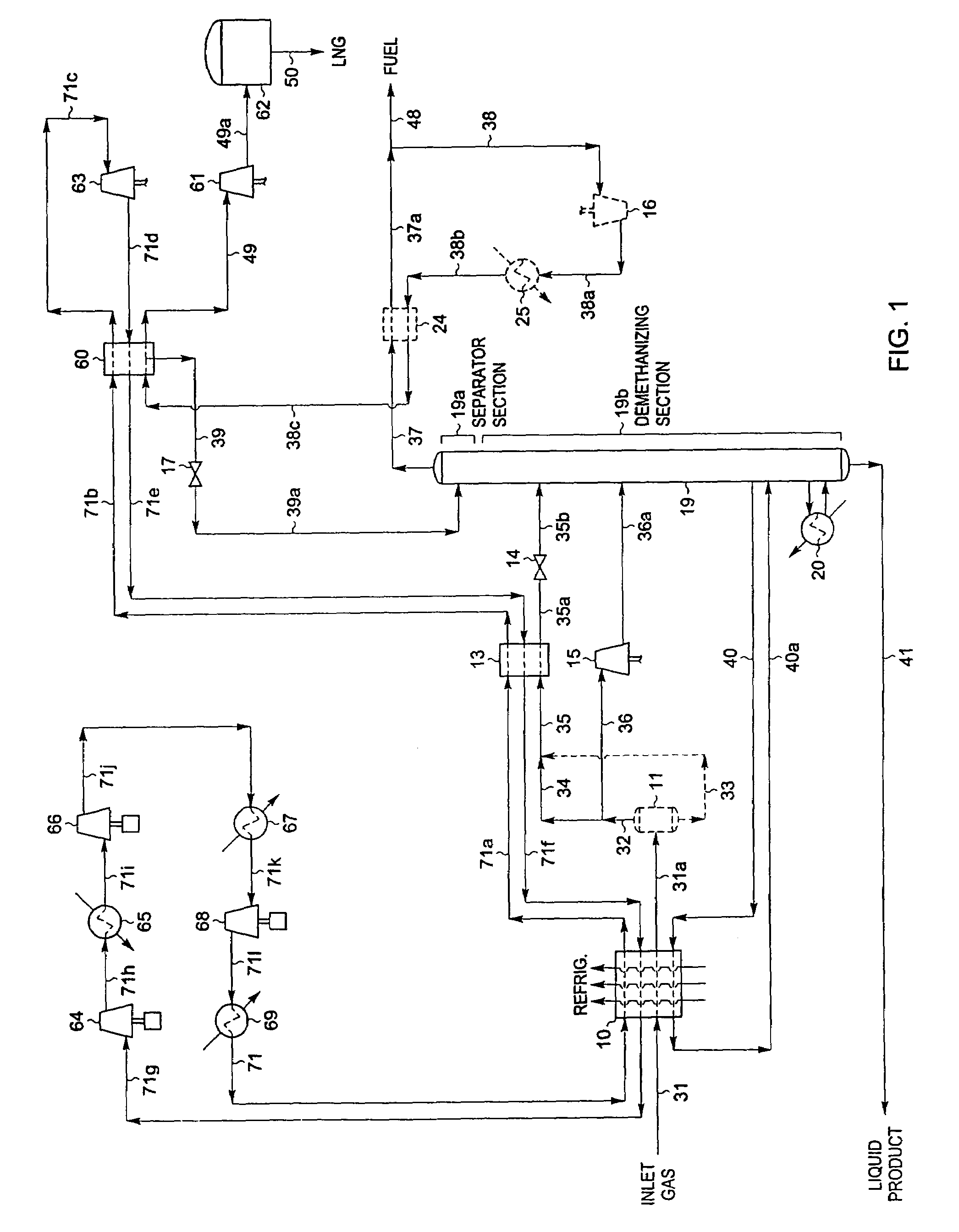
[0034]Referring now to FIG. 1, we begin with an illustration of a process in accordance with the present invention where it is desired to produce an NGL co-product containing the majority of the ethane and heavier components in the natural gas feed stream. In this simulation of the present invention, inlet gas enters the plant at 90° F. [32° C.] and 1285 psia [8,860 kPa(a)] as stream 31. If the inlet gas contains a concentration of carbon dioxide and / or sulfur compounds which would prevent the product streams from meeting specifications, these compounds are removed by appropriate pretreatment of the feed gas (not illustrated). In addition, the feed stream is usually dehydrated to prevent hydrate (ice) formation under cryogenic conditions. Solid desiccant has typically been used for this purpose.
[0035]The feed stream 31 is cooled in heat exchanger 10 by heat exchange with refrigerant streams and demethanizer side reboiler liquids at −68° F. [−55° C.] (stream 40). Note that in all cas...
example 2
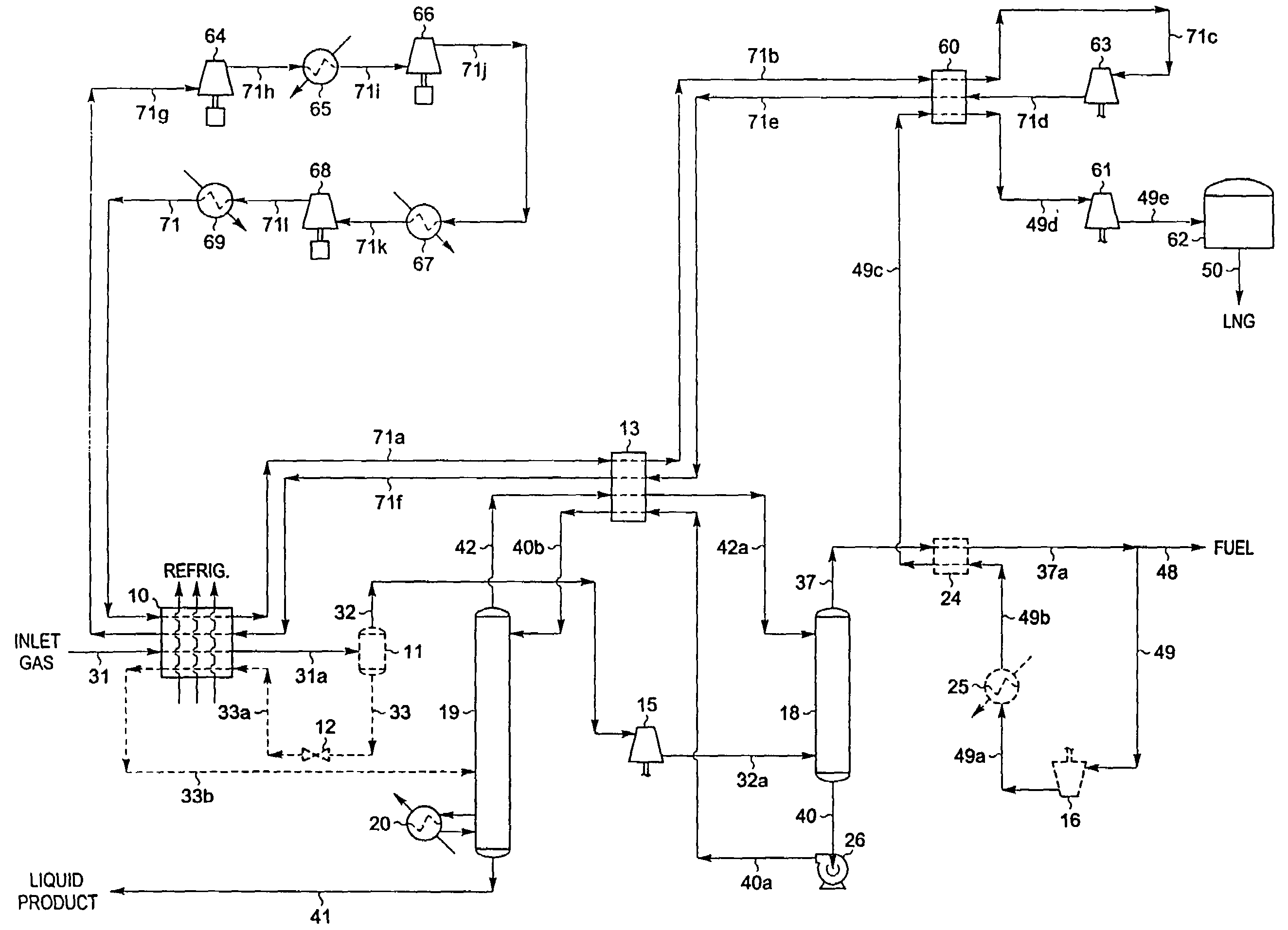
[0051]If the specifications for the LNG product will allow more of the ethane contained in the feed gas to be recovered in the LNG product, a simpler embodiment of the present invention may be employed. FIG. 3 illustrates such an alternative embodiment. The inlet gas composition and conditions considered in the process presented in FIG. 3 are the same as those in FIG. 1. Accordingly, the FIG. 3 process can be compared to the embodiment displayed in FIG. 1.
[0052]In the simulation of the FIG. 3 process, the inlet gas cooling, separation, and expansion scheme for the NGL recovery section is essentially the same as that used in FIG. 1. Inlet gas enters the plant at 90° F. [32° C.] and 1285 psia [8,860 kPa(a)] as stream 31 and is cooled in heat exchanger 10 by heat exchange with refrigerant streams and demethanizer side reboiler liquids at −35° F. [−37° C.] (stream 40). The cooled stream 31a enters separator 11 at −30° F. [−34° C.] and 1278 psia [8,812 kPa(a)] where the vapor (stream 32)...
example 3
[0064]If the specifications for the LNG product will allow all of the ethane contained in the feed gas to be recovered in the LNG product, or if there is no market for a liquid co-product containing ethane, an alternative embodiment of the present invention such as that shown in FIG. 4 may be employed to produce an LPG co-product stream. The inlet gas composition and conditions considered in the process presented in FIG. 4 are the same as those in FIGS. 1 and 3. Accordingly, the FIG. 4 process can be compared to the embodiments displayed in FIGS. 1 and 3.
[0065]In the simulation of the FIG. 4 process, inlet gas enters the plant at 90° F. [32° C.] and 1285 psia [8,860 kPa(a)] as stream 31 and is cooled in heat exchanger 10 by heat exchange with refrigerant streams and flashed separator liquids at −46° F. [−43° C.] (stream 33a). The cooled stream 31a enters separator 11 at −1° F. [−18° C.] and 1278 psia [8,812 kPa(a)] where the vapor (stream 32) is separated from the condensed liquid (...
PUM
 Abstract
Description
Claims
Application Information
 - R&D
- Intellectual Property
- Life Sciences
- Materials
- Tech Scout
- Unparalleled Data Quality
- Higher Quality Content
- 60% Fewer Hallucinations
Browse by: Latest US Patents, China's latest patents, Technical Efficacy Thesaurus, Application Domain, Technology Topic, Popular Technical Reports.
© 2025 PatSnap. All rights reserved.Legal|Privacy policy|Modern Slavery Act Transparency Statement|Sitemap|About US| Contact US: help@patsnap.com


