Incidence matrix-based distribution network traveling wave fault localization method

A correlation matrix, traveling wave fault technology, applied in fault location, fault detection by conductor type, measurement of electricity, etc., can solve problems such as bad data identification

Active Publication Date: 2017-02-22
国网新疆电力有限公司巴州供电公司 +1
View PDF5 Cites 13 Cited by
  • Summary
  • Abstract
  • Description
  • Claims
  • Application Information

AI Technical Summary

Problems solved by technology

[0008] The present invention provides a distribution network traveling wave fault location method based on an association matrix, which overcomes the shortcomings of the distribution network fault location method in the prior art, and can effectively solve the problems in the distribution network location in the prior art. bad data identification problem

Method used


Image

  • Incidence matrix-based distribution network traveling wave fault localization method
  • Incidence matrix-based distribution network traveling wave fault localization method
  • Incidence matrix-based distribution network traveling wave fault localization method

Examples


Embodiment 1

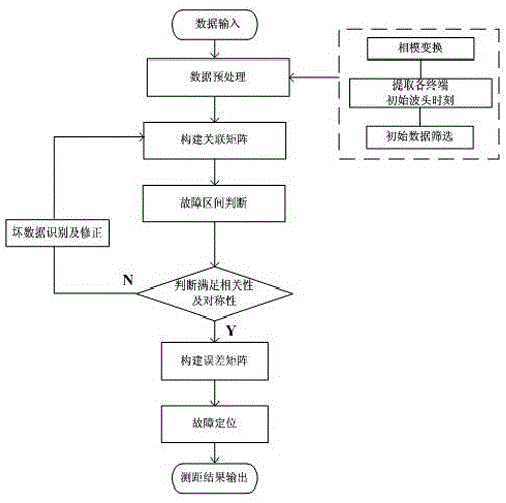
[0054] Embodiment 1: as attached figure 1 , 2 As shown, the distribution network traveling wave fault location method based on the correlation matrix includes the following steps:

[0055] The first step is to input data and perform data preprocessing, including (1) phase-mode transformation. Due to the coupling of transient traveling waves in the transmission process of transmission lines, in order to reduce the influence of phase-to-phase coupling, Clark transformation is used to transform the three-phase voltage to obtain α , β, and 0 moduli, select α modulus for analysis; (2) find the initial moment of fault, use wavelet transform to detect the sudden change point of transient voltage signal, and use it as the initial fault moment of each measurement node; (3) screen abnormal nodes, according to The measured initial fault time and amplitude screen the nodes to exclude obviously abnormal nodes;

[0056] The second step is to construct an association matrix. Each backbone ...

Embodiment 2

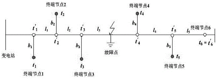
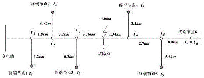
[0092] Embodiment 2: as attached image 3 As shown, the simulation model was built based on the actual 10kV distribution network line, in which the main line length is 11.4km, and positioning terminal devices are installed at the end of the line and the ends of five main branch lines. The sampling rate is 1.25MHz. The transmission line model refers to The actual line is built, and the fault point is at the distance t' from the main line 3 at 3.26km. The fault location calculation follows the following steps:

[0093] Step 1: Phase-mode transformation extracts the α modulus for analysis, and extracts the initial fault moment of each terminal node through wavelet transformation [t 1 , t 2 , t 3 , t 4 , t 5 , t 6 ] and filter the data;

[0094] Step 2: Calculate the backbone node time [t' according to the initial failure time of the actual terminal node 1 , t' 2 , t' 3 , t' 4 , t' 5 , t'6 ]=[87076.8, 87070.5, 87059.4, 87052.8, 87063, 87065.2];

[0095] Step 3: Const...


PUM


Abstract

The invention relates to the technical field of power system automation and particularly relates to an incidence matrix-based distribution network traveling wave fault localization method which comprises the following steps of: (I) preprocessing data; (II) establishing an incidence matrix; (III) judging the fault section; (IV) judging whether the vector element meets the correlation and symmetry; (V) identifying bad data; and (VI) establishing an error matrix, localizing the fault and outputting the ranging result. In the invention, based on the error overall distribution principle and by establishing an error matrix, the fault localization result with minimum overall error in all nodes is found, and the overall precision of fault localization is improved. In the invention, the incidence matrix is established by use of multi-end data, the fault section is determined and abnormal device data is identified according to the symmetry and correlation of the incidence matrix, and accurate localization of the fault point is further finished accordingly, and the fault localization reliability and precision of a distribution network are improved.

Description

technical field [0001] The invention relates to the technical field of power system automation, and relates to a method for locating traveling wave faults in distribution networks based on an association matrix. Background technique [0002] The medium and low voltage distribution network in my country is 3 to 66kV, and the small current grounding system is mostly used, that is, the neutral point is not grounded or the operation mode is grounded through the arc suppression coil. The small current grounding system has high power supply reliability, but after the line fault, the fault current is weak, which makes it more difficult to locate the fault in the distribution network. [0003] At present, the main research direction in the field of distribution network fault location is fault section location, which can be divided into two types according to different principles: active location method and passive location method. The passive positioning method generally uses FTU o...

Claims


Application Information

Patent Timeline
Patent Type & Authority Applications(China)
IPC IPC(8): G01R31/08
CPCG01R31/086G01R31/088
Inventor 徐波陈旭崔立忠刘肖骢郭宁明杜向楠
Owner 国网新疆电力有限公司巴州供电公司
Why Eureka
Try Eureka