A Method for On-orbit Vibration Analysis of Spaceborne Antenna with Cable Net Reflector

A technology of cable-net reflectors and space-borne antennas, applied to instruments, design optimization/simulation, calculations, etc., can solve problems such as time-consuming and labor-consuming, low efficiency, and poor connection of analysis models, so as to avoid repetitive operations and realize The effect of automatic transmission and simplified geometric description

Active Publication Date: 2019-11-19
XIDIAN UNIV
View PDF5 Cites 0 Cited by
  • Summary
  • Abstract
  • Description
  • Claims
  • Application Information

AI Technical Summary

Problems solved by technology

[0004] (1) Most of the traditional modeling is to model a single entity model, which cannot take into account the integrity and systematicness of the entire antenna model
[0005] (2) The models are relatively independent during the analysis of each field, which will lead to poor cohesion of the analysis model, and cannot reflect the characteristics of multi-field coupling of the antenna system
[0006] (3) The traditional analysis of the thermal load of the antenna on orbit only considers its thermally induced deformation under the action of temperature load, ignoring the characteristics of its thermally induced transient vibration
Obviously, this method of analyzing the electrical performance of the antenna during on-orbit vibration is inefficient, time-consuming and labor-intensive, and each calculation is just a superposition operation of static deformation, which cannot reflect the characteristics of the antenna's electrical performance during on-orbit vibration.

Method used


Image

  • A Method for On-orbit Vibration Analysis of Spaceborne Antenna with Cable Net Reflector
  • A Method for On-orbit Vibration Analysis of Spaceborne Antenna with Cable Net Reflector
  • A Method for On-orbit Vibration Analysis of Spaceborne Antenna with Cable Net Reflector

Examples


Embodiment Construction

[0049] In order to make the object, technical solution and advantages of the present invention more clear, the present invention will be further described in detail below in conjunction with the examples. It should be understood that the specific embodiments described here are only used to explain the present invention, not to limit the present invention.

[0050] The application principle of the present invention will be described in detail below in conjunction with the accompanying drawings.

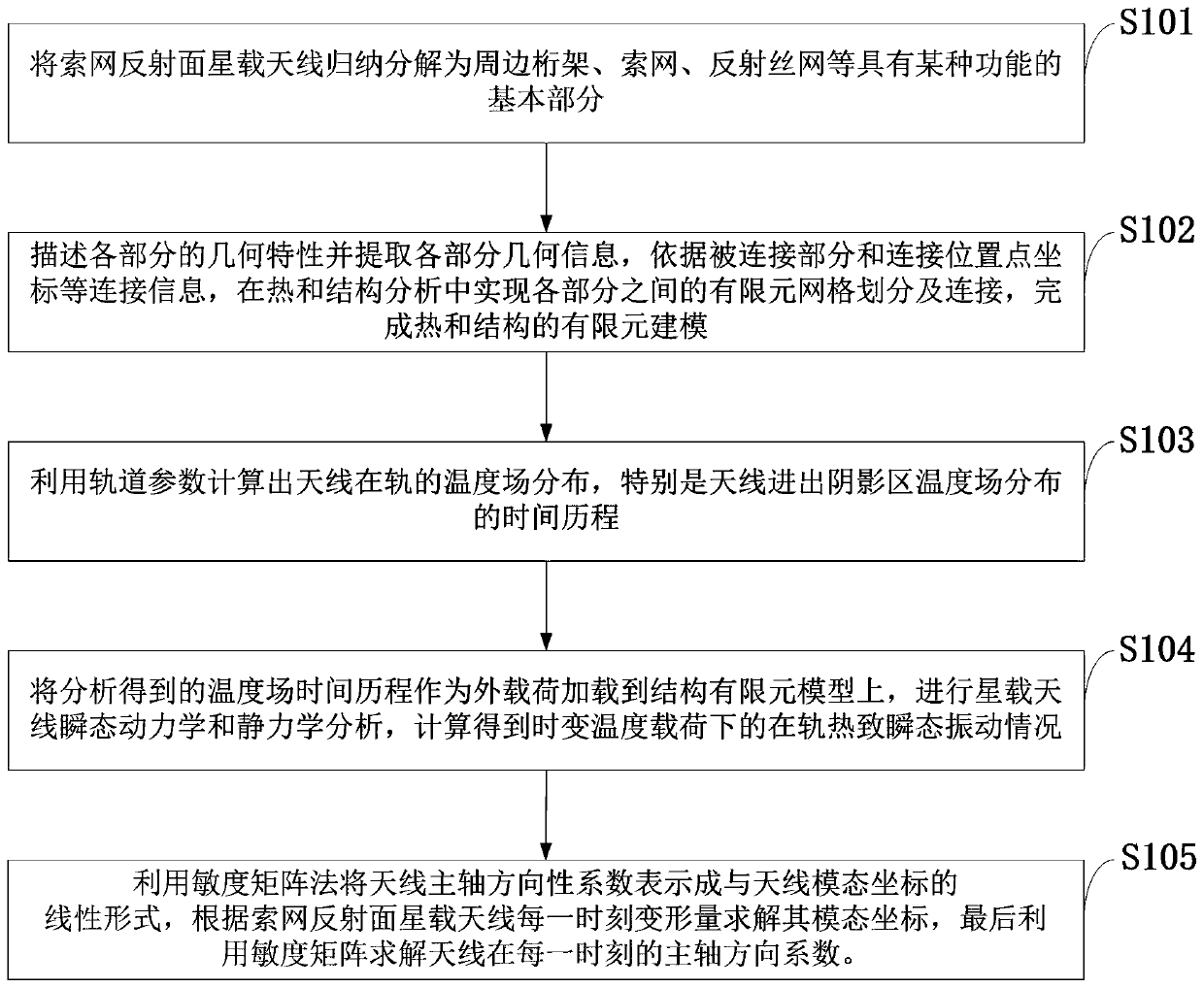
[0051] Such as figure 1 As shown, the on-orbit vibration analysis method of the cable net reflector spaceborne antenna of the embodiment of the present invention comprises the following steps:

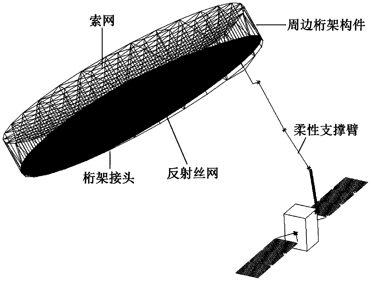
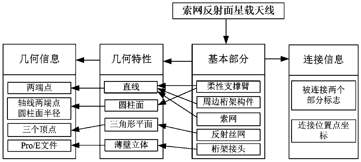
[0052] S101: Inductively decompose the cable net reflector spaceborne antenna into basic parts with certain functions such as surrounding trusses, cable nets, and reflective wire mesh;

[0053] S102: Describe the geometric characteristics of each part and extract the geometric information of ...


PUM


Abstract

The invention discloses a method for analyzing in-orbit vibration of a cable-mesh reflector space-borne antenna. The method comprises the following steps: inducing and resolving the cable-mesh reflector space-borne antenna into basic parts with certain functions; describing the geometrical features of each part and extracting the geometrical information of each part to complete finite element modeling of heat and structure; calculating the antenna in-orbit temperature field distribution and the time history of temperature field distribution of antenna entering and exiting a shadow region by utilizing orbit parameters; performing transient dynamic analysis and static analysis of the space-borne antenna, and calculating thermotropic transient vibration; establishing the linear approximate relation of electrical performance and vibration features; and determining the electrical performance variation when the antenna enters and exits the shadow region. The method realizes quick modeling to improve the analysis efficiency of in-orbit vibration of the cable-mesh reflector space-borne antenna; main geometrical information of the antenna can be described by simple lines and areas, so that the geometrical description of the antenna structure is simplified, and partition of finite element meshes in multi-field analysis can be benefited.

Description

technical field [0001] The invention belongs to the technical field of radar antennas, and in particular relates to an on-orbit vibration analysis method of a cable-net reflector space-borne antenna. Background technique [0002] At present, the cable net reflector antenna is one of the indispensable equipment in the field of national defense and aerospace. Due to its huge advantages in size and quality, the cable net reflector antenna is frequently used on various satellites and other spacecraft for space exploration, satellite Communications, earth observation, electronic reconnaissance and other fields. In the harsh outer space environment, the large-scale deployable antenna structure periodically experiences the sunshine area and shadow area of ​​±200°C, resulting in periodic thermal deformation and thermal stress of the structure. Especially when entering and leaving the shadow area, the thermal load acting on the antenna will have a sudden change, which will cause the...

Claims


Application Information

Patent Timeline
Patent Type & Authority Patents(China)
IPC IPC(8): G06F17/50
CPCG06F30/23G06F2113/16
Inventor 葛东明杜敬利张岳震李海洋张逸群杨东武
Owner XIDIAN UNIV
Why Eureka
Try Eureka