
Double-loop grid-connected control method for z-source inverter based on repetitive proportional resonance control

A technology of proportional resonance control and source inverter, which is applied in the direction of AC network circuit, single-network parallel feeding arrangement, output power conversion device, etc., can solve the problem of high-speed transient response of input and output, light weight and high efficiency. , high power factor, limited system steady-state margin, limited system resonance peak, etc., to achieve the effect of wide application range, error-free tracking, and reduced switch stress

Active Publication Date: 2019-06-11
SHANGHAI UNIVERSITY OF ELECTRIC POWER
View PDF7 Cites 0 Cited by
  • Summary
  • Abstract
  • Description
  • Claims
  • Application Information

AI Technical Summary

Problems solved by technology

However, when proportional-integral control is used in the two-phase rotating coordinate system, since the gain of proportional integral at the fundamental frequency of the power grid is limited, steady-state errors and harmonic interference will occur when tracking sinusoidal signals, which will affect the entire system Operating at unity power factor contributes to
[0007] 3. Under the traditional double-loop proportional-integral control, the resonance peak value of the system is limited, and the steady-state margin of the system is limited
[0008] In view of the above reasons, the control method of the traditional double-loop control three-phase grid-connected inverter is difficult to meet the technical indicators of input and output high-speed transient response, light weight, high efficiency, and high power factor

Method used


Image

  • Double-loop grid-connected control method for z-source inverter based on repetitive proportional resonance control
  • Double-loop grid-connected control method for z-source inverter based on repetitive proportional resonance control
  • Double-loop grid-connected control method for z-source inverter based on repetitive proportional resonance control

Examples


Embodiment Construction

[0052] The present invention will be described in detail below in conjunction with the accompanying drawings and specific embodiments. This embodiment is carried out on the premise of the technical solution of the present invention, and detailed implementation and specific operation process are given, but the protection scope of the present invention is not limited to the following embodiments.

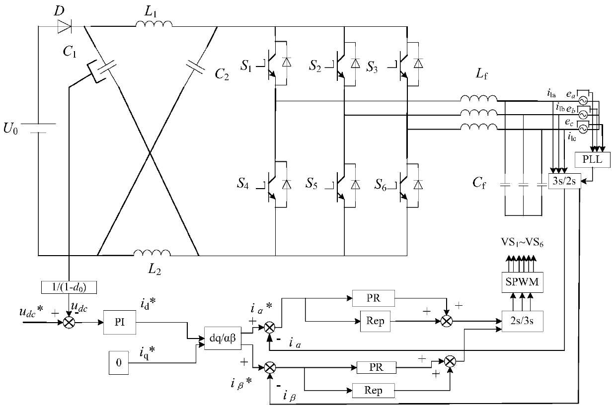
[0053] The control structure of LC-type three-phase Z-source inverter based on repetitive proportional resonance control is as follows: figure 1 shown, the capacitor C 1 、C 2 , inductance L 1 , L 2 , switch tube S 1 -S 6 , inductance group L f , capacitor bank C f Composed of LC-type three-phase Z-source inverter, U 0 is the input supply voltage.

[0054] The Z-source inverter double-loop grid-connected control method based on repetitive proportional resonance control includes the following steps:

[0055] 1) Obtain the current reference value of the αβ axis according to the...


PUM


Abstract

The invention relates to a Z source inverter double loop grid-connected control method based on repetitive proportional resonant control. The method is used for an LC type Z source inverter grid-connected system. The method comprises the steps of 1, obtaining circuit reference values at an alpha and beta axis according to acquired capacitor and voltage in a Z source inverter; 2, obtaining circuit feedback values at the alpha and beta axis according to acquired grid side inductive current; 3, adding difference values of the circuit reference values and the circuit values after the circuit reference values and the circuit values pass through a repetitive controller and a proportional resonant controller respectively to obtain circuit values of repetitive proportional resonant control, and inputting the obtained circuit values into an SPWM module. Compared with the prior art, waveform quality of grid-connected circuit and voltage under the LC type filter is improved, harmonic distortion rate is reduced, pressure raising effect is drastically improved, system structure is simplified, and use of related materials is saved.

Description

technical field [0001] The invention relates to a Z-source inverter double-loop grid-connected control method, in particular to a Z-source inverter double-loop grid-connected control method based on repeated proportional resonance control. Background technique [0002] At present, the problem of energy shortage is becoming more and more serious, and the utilization of new energy sources such as wind energy and solar energy is imminent. The grid-connected inverter is the key equipment for connecting new energy and the large power grid, and plays a very important role in the entire system. [0003] Traditional inverters are usually voltage-type inverters, which themselves are step-down inverters. When the output voltage of the inverter bridge is required to be higher, it is usually necessary to add an amplifier circuit at the front end of the inverter, which leads to an increase in system cost and a more complicated control structure. As a new topology, the Z-source inverter...

Claims


Application Information

Patent Timeline
Patent Type & Authority Patents(China)
IPC IPC(8): H02J3/38H02M7/5387
CPCH02J3/382H02J3/383H02J3/386H02M7/5387Y02B70/10Y02E10/56Y02E10/76
Inventor 杨旭红王毅舟
Owner SHANGHAI UNIVERSITY OF ELECTRIC POWER
Learn More