
Dynamic recording device and method for power system

A dynamic recording and power system technology, applied in the direction of circuit devices, electrical components, etc., can solve the problem of low efficiency in transmitting a large amount of information, and achieve the effect of improving overall performance, improving efficiency, and enhancing real-time performance

Inactive Publication Date: 2017-02-22
XUCHANG XJ SOFTWARE TECH +3
View PDF3 Cites 3 Cited by
  • Summary
  • Abstract
  • Description
  • Claims
  • Application Information

AI Technical Summary

Problems solved by technology

[0006] The purpose of the present invention is to provide a dynamic recording device and method for power systems, which is used to solve the problem of low efficiency of transmitting large amounts of information in existing dynamic recording devices

Method used


Image

  • Dynamic recording device and method for power system
  • Dynamic recording device and method for power system

Examples


Embodiment Construction

[0033] The specific embodiments of the present invention will be further described below in conjunction with the accompanying drawings.

[0034] An embodiment of a power system dynamic recording device of the present invention:

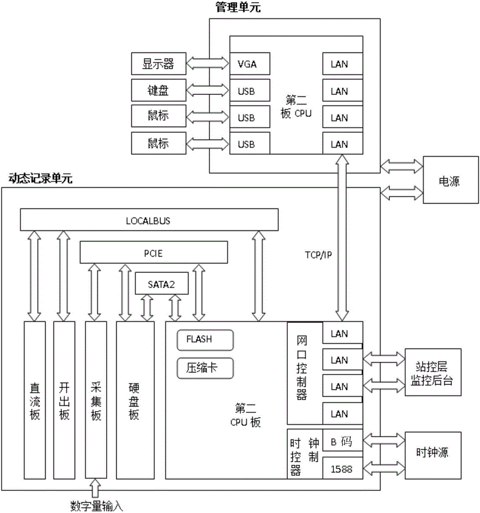
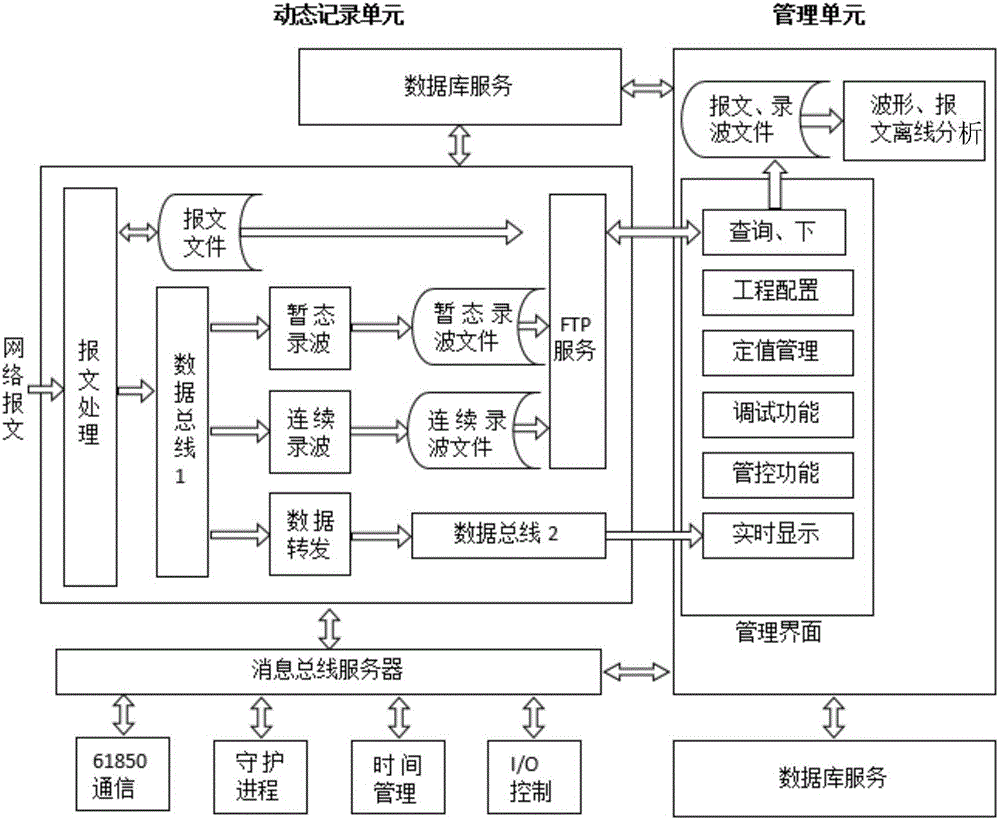
[0035] The power system dynamic recording device of the present invention includes a dynamic recording unit and a management unit, wherein the dynamic recording unit includes a message processing module, a transient wave recording module, a continuous wave recording module, a data forwarding module, a 61850 communication module, a time management module, I / O control modules and daemon modules, such as figure 2 shown.

[0036] Wherein, the message processing module is used for analyzing the collected network message, and the analyzed data is packed and transmitted to the first data bus based on DBus technology. The message file of the message processing module is transmitted to the management unit through the FTP service module.

[0037] The transi...


PUM


Abstract

The invention relates to a dynamic recording device and method for a power system. The device comprises a dynamic recording unit and a managing unit, wherein the dynamic recording unit comprises a message processing module, a transient wave recording module, a continuous wave recording module, a data forwarding module, a 61850 communication module, a time management module, an I / O control module and a daemon module. By constructing a first data bus and a second data bus which are used for data transmission in the dynamic recording unit and between the dynamic recording unit and the managing unit respectively, data in the device can be effectively organized and distributed, high-speed and stable transmission of the data in the device is achieved, and the properties of the device are improved.

Description

technical field [0001] The invention belongs to the field of power system automation, and in particular relates to a power system dynamic recording device and method. Background technique [0002] The dynamic recording device is an indispensable precision equipment in the dynamic recording process of the power system, and it is an important basis for evaluating the action behavior of relay protection and analyzing the nature and cause of equipment failure. Its main task is to automatically and accurately record the changes of various electrical quantities in the whole process of the fault when a fault occurs in the power system, and analyze and process the recorded electrical quantities, so as to accurately judge and deal with the fault and ensure the safety, stability and reliability of the power system. run. [0003] Traditional dynamic recording devices have problems such as low hardware configuration, small system capacity, and poor practicability, which cannot meet the...

Claims


Application Information

Patent Timeline
IPC IPC(8): H02J13/00
CPCH02J13/0013H02J13/0062
Inventor 杨坤刘小燕刘永华李贞窦中山王兴安张秀娟王四伟陈强熊焰张玉垒李义清李长耿卜银娜戚振伟
Owner XUCHANG XJ SOFTWARE TECH
Learn More