Hybrid beam forming method and device in blind channel

A technology of beamforming and hybrid beam, which is applied in the field of hybrid beamforming under blind channels, can solve the problems of high complexity, lack of versatility, difficulty in obtaining channel state information, etc., and achieve the goal of reducing computational complexity and strong practicability Effect

Active Publication Date: 2017-02-22
BEIJING UNIV OF POSTS & TELECOMM
View PDF5 Cites 25 Cited by
  • Summary
  • Abstract
  • Description
  • Claims
  • Application Information

AI Technical Summary

Problems solved by technology

However, there are some challenges in the actual system, which mainly include: 1) It is necessary to estimate the complete channel state information, but there are great difficulties and challenges in obtaining channel state information in the millimeter-wave large-scale antenna scenario
There are two reasons: on the one hand, it is very difficult to estimate the channel matrix H in the low receiving SNR state before beamforming; on the other hand, the complexity of estimating the beam departure direction DOA and beam arrival direction DOD is too high, and some current classical estimates The relationship between the algorithm and the number of paths propagated by the channel is cubic
2) It is necessary to perform SVD decomposition on the high-dimensional channel matrix H, which has high complexity
3) Classical methods such as the Sparse Precoding method will fail in the LOS (line of sight, line of sight) channel state and are not universal

Method used


Image

  • Hybrid beam forming method and device in blind channel
  • Hybrid beam forming method and device in blind channel
  • Hybrid beam forming method and device in blind channel

Examples


Embodiment Construction

[0070] In order to make the objectives, technical solutions, and advantages of the present invention clearer, the following further describes the present invention in detail in conjunction with specific embodiments and with reference to the accompanying drawings.

[0071] It should be noted that all the expressions "first" and "second" in the embodiments of the present invention are used to distinguish two entities with the same name but not the same or parameters that are not the same, as shown in "first" and "second" Only for the convenience of presentation, it should not be construed as a limitation to the embodiments of the present invention, and subsequent embodiments will not describe this one by one.

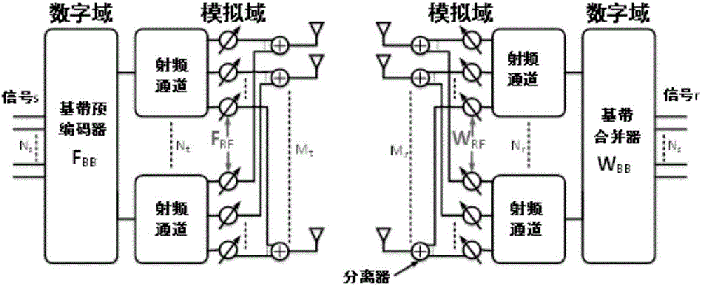
[0072] Think first figure 1 The scenario and parameter settings of the hybrid beamforming system under the 5G millimeter wave MIMO system are shown. The basic idea of ​​hybrid beamforming design is to solve the four analog domain / digital domain precoding / combining matrices tha...


PUM


Abstract

The invention discloses a hybrid beam forming method and device in a blind channel. The method comprises the following steps of: on the premise that the receiving signal-to-noise ratio is low and the receiving signal power is maximized, solving by adopting a stochastic gradient descent method according to the solving thought of a Rrassmann space packing problem, so that a simulation-domain beam forming pre-coding matrix of a base station side and a simulation-domain beam forming combination matrix of a user side are obtained; and, in combination with the simulation-domain beam forming pre-coding matrix of the base station side and the simulation-domain beam forming combination matrix of the user side, finding the optimal solution of a digital-domain equivalent channel matrix by adopting a transceiving iterative method based on the time-division duplex channel reciprocity, so that a digital-domain beam forming pre-coding matrix of the base station side and a digital-domain beam forming combination matrix of the user side are obtained. The hybrid beam forming method and device in the blind channel provided by the invention work in a blind channel state; channel state information does not need to be obtained in advance; the method and the device are not limited by channel types; therefore, the computing complexity is greatly reduced; and thus, the method and the device have relatively high practicability.

Description

Technical field [0001] The invention relates to the field of hybrid beamforming under massive MIMO, in particular to a hybrid beamforming method and device under blind channels. Background technique [0002] The millimeter wave communication system is widely concerned and applied in the field of ultra-high-speed and wireless short-distance communication with its rich unlicensed spectrum resources, good international versatility, high speed, and large bandwidth. Beamforming technology is a combination of antenna technology and digital signal processing technology for directional signal transmission or reception. Generally, beamforming is divided into two types: analog domain beamforming and digital domain beamforming. Although the full digital domain beamforming with a large-scale antenna array has the best performance, it requires the transceiver end to have the same number of radio frequency channels as the number of antennas, and there is a large power loss and implementation ...

Claims


Application Information

Patent Timeline
Patent Type & Authority Applications(China)
IPC IPC(8): H04B7/0413H04B7/06H04B7/08
CPCH04B7/0413H04B7/043H04B7/0456H04B7/0617H04B7/086H04B7/0868
Inventor 吴伟刘丹谱吴惠文张志龙尹长川
Owner BEIJING UNIV OF POSTS & TELECOMM
Why Eureka
Try Eureka