
LED lamp power supply capable of reducing power at regular time

An LED lamp and power reduction technology, which is applied in the field of timed power reduction LED lamp power supply, can solve the problems of increasing production cost, increasing energy loss, increasing environmental pollution, etc., to facilitate installation and disassembly, reduce energy loss, The effect of reducing the cost of use

Active Publication Date: 2017-02-22
中山市恒能电子科技有限公司
View PDF10 Cites 0 Cited by
  • Summary
  • Abstract
  • Description
  • Claims
  • Application Information

AI Technical Summary

Problems solved by technology

[0003] In the prior art, there is no short-circuit protection mechanism installed in the traditional traditional LED lamp power supply, resulting in that the circuit cannot be automatically shut down and cannot automatically alarm when the circuit is short-circuited, which will easily lead to damage to the main components of the circuit, increase the production cost, and easily Cause a fire, the traditional LED lamp power supply does not have a timing power reduction mechanism, resulting in the LED lamp usually using a constant power to work, resulting in the inability to intelligently regulate the LED lamp power supply, increasing energy loss, wasting non-renewable energy, and increasing pollution to the environment

Method used


Image

  • LED lamp power supply capable of reducing power at regular time
  • LED lamp power supply capable of reducing power at regular time
  • LED lamp power supply capable of reducing power at regular time

Examples


specific Embodiment approach

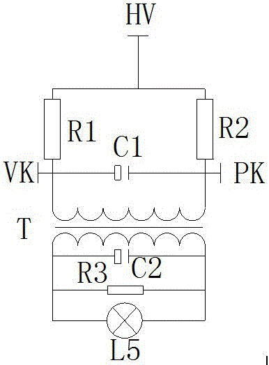
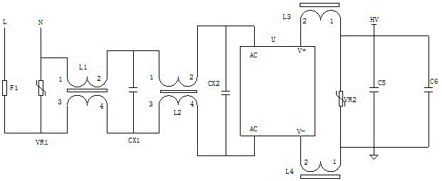
[0027]Specific implementation method: when the main body of the circuit is energized and running, the short circuit protection mechanism works, the live wire L transmits the current to the fuse F1, and then the fuse F1 transmits the current to the rectifier transformer L1, and then the rectifier transformer L1 transmits the current to the rectifier transformer L2 and Capacitor CX1, then the rectifier transformer L2 sends the current to the rectifier U, and then the rectifier U sends the current to the main body of the circuit. When the main body of the circuit is short-circuited, the rectifier U receives the short-circuit signal and sends out an instruction, the capacitor CX1 and the capacitor CX2 are disconnected, and the fuse F1 stop working, the design realizes the short circuit protection of the main body of the circuit.

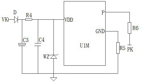
[0028] When the LED lamp L5 works for four hours, the PWM regulator U1M works and sends an instruction, the value of the resistor R6 becomes larger, the ...


PUM


Abstract

The invention provides an LED lamp power supply capable of reducing power at a regular time. The LED lamp power supply comprises a fuse F1, a rectifier transformer L1, a capacitor CX1, a filter U, a rectifier transformer L3, a sliding resistor VR2, a diode D, a resistor R4, a filter capacitor C3, a triode DW, a PWM regulator U1M and a resistor R6, wherein the right end of the fuse F1 is connected with the rectifier transformer L1; the right end of the rectifier transformer L1 is connected with the capacitor CX1; the filter U is mounted at the right end of the capacitor CX1; the right end of the filter U is connected with the rectifier transformer L3; the right end of the rectifier transformer L3 is connected with the sliding resistor VR2; through such a design, protection for the main body of a circuit is achieved; the right end of the diode D is connected with the resistor R4 and the filter capacitor C3 respectively; the right end of the resistor R4 is connected with the triode DW and the PWM regulator U1M respectively; the right end of the PWM regulator U1M is connected with the resistor R6; through such a design, regulation of the output power of a LED lamp L5 is achieved. The LED lamp power supply is convenient to operate, can protect the circuit, can carry out intelligent control, and is convenient to detach, good in stability and high in reliability.

Description

technical field [0001] The invention is a power supply for LED lamps with timing power reduction, which belongs to the field of LED lamp power supply equipment. Background technique [0002] LED power supply is a kind of power supply. It is a device that provides power to electronic equipment, also known as a power supply. It is deployed as a different power input on the device connected to an independent circuit device with two or three power inputs. Dry batteries, etc. are also called power supplies; devices that convert alternating current into direct current through transformers and rectifiers are called rectified power supplies. [0003] In the prior art, there is no short-circuit protection mechanism installed in the traditional traditional LED lamp power supply, resulting in that the circuit cannot be automatically shut down and cannot automatically alarm when the circuit is short-circuited, which will easily lead to damage to the main components of the circuit, incre...

Claims


Application Information

Patent Timeline
IPC IPC(8): H05B33/08H05B44/00
CPCH05B45/50H05B45/00Y02B20/30
Inventor 杨赐钦蒋怀军
Owner 中山市恒能电子科技有限公司
Learn More