Tubular motor, brushless motor control method, and motor with brake

A control method and brake technology, which is applied in the control field of motors with brakes, tubular motors, and brushless motors, can solve the problems of low assembly efficiency of tubular motors, and achieve the effect of reducing the number of parts, reducing costs, and efficient assembly

Inactive Publication Date: 2017-02-22
SANKYO SEIKI MFG CO LTD
View PDF7 Cites 3 Cited by
  • Summary
  • Abstract
  • Description
  • Claims
  • Application Information

AI Technical Summary

Problems solved by technology

Therefore, there is a problem that the assembly efficiency of the tubular motor is low

Method used


Image

  • Tubular motor, brushless motor control method, and motor with brake
  • Tubular motor, brushless motor control method, and motor with brake
  • Tubular motor, brushless motor control method, and motor with brake

Examples


Embodiment Construction

[0093] (first invention)

[0094] Using paragraphs (0054) to (0088), (0175) and Figure 1 to Figure 6 The first invention will be described.

[0095] Hereinafter, a tubular motor to which the present invention is applied will be described with reference to the drawings. In the following description, L is attached to the motor axis, L1 is attached to the output side where the motor shaft protrudes, and L2 is attached to the side opposite to the side where the motor shaft protrudes (opposite output side).

[0096] (the whole frame)

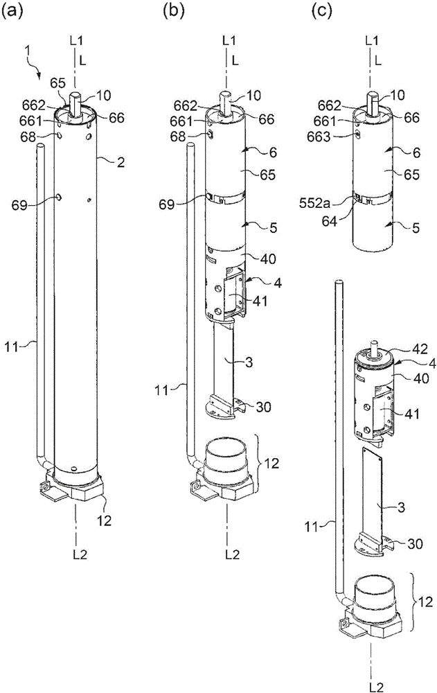
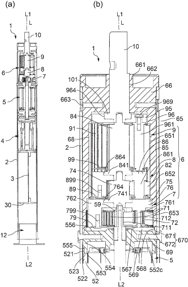
[0097] figure 1 is an explanatory diagram of a tubular motor 1 to which the present invention is applied, figure 1 (a), (b), and (c) are a perspective view of the tubular motor 1 , a perspective view of the tubular motor 1 with the casing 2 omitted, and an exploded perspective view of a unit housed inside the casing. figure 2 is a sectional view of a tubular motor 1 to which the present invention is applied, figure 2 (a) and (b) are cross-...


PUM


Abstract

The present invention provides a tubular motor that has a reduced number of components and that can be efficiently assembled even when a recess portion is provided in an output-side end face of an output-side end plate portion of a motor unit. For example, in a tubular motor 1, a planetary carrier 75 of a first planetary gear unit 7 is provided with a support plate 79 overlapping a planetary gear 71 on an anti-output-side L2 and supporting the planetary gear 71 from the anti-output-side L2. Thus, the first planetary gear unit 7 is independent as a first planetary gear unit, and there is no need to support the planetary gear 71 with an output-side end plate portion 55 and the like of a motor unit 5. Accordingly, even when an output-side end face 556 of the output-side end plate portion 55 is provided with a recess portion 569 to which grease leaking from the first planetary gear unit 7 flows, the first planetary gear unit 7 can be disposed directly adjacent to the output side of the motor unit 5.

Description

technical field [0001] The present invention (first invention) relates to a tubular motor in which a motor unit and a planetary gear unit are arranged in an axial direction inside a cylindrical case. [0002] The present invention (second invention) relates to a method of controlling a brushless motor used in an electric roller blind device or the like. [0003] The present invention (third invention) relates to a motor with a brake including a built-in brake for applying a braking force to a motor shaft. Background technique [0004] (first invention) [0005] In a tubular motor used for winding a curtain such as a roller blind or a blind, a motor unit and a planetary gear unit are arranged in the axial direction inside a cylindrical case (see Patent Document 1). In Patent Document 1 image 3 In the described tubular motor, the planetary gear unit is arranged directly adjacent to the output side of the partition wall, and the planetary gear rotates in a state supported by...

Claims


Application Information

Patent Timeline
Patent Type & Authority Applications(China)
IPC IPC(8): H02K7/116B65H18/10F16D55/36F16D65/18F16H1/46H02K7/102H02P3/04H02P3/22H02P6/24F16D121/22
CPCF16H1/46F16D55/36H02P3/04H02P3/22H02P6/24H02K7/116H02K2207/03H02K7/1163B65H18/10F16D65/18H02K7/102H02K11/215
Inventor 安藤正明吉川伸一中村五郎黑沢博德鲇泽优武田正芦部昇
Owner SANKYO SEIKI MFG CO LTD
Why Eureka
Try Eureka