Lathe dedusting device

A technology of a dust removal device and a lathe, which is applied in the field of lathes, can solve the problems of reducing production efficiency, error of processing results, etc., and achieves the effects of simple structure, good dust removal effect, and easy use.

Inactive Publication Date: 2017-03-08
湖南衡泰机械科技有限公司
View PDF5 Cites 1 Cited by
  • Summary
  • Abstract
  • Description
  • Claims
  • Application Information

AI Technical Summary

Problems solved by technology

However, with the rapid development of CNC lathes, each manufacturer's requirements for appearance are becoming more and more beautiful. As an end user, beauty is important, and more importantly, product accuracy and processing efficiency. As long as the processing error is reduced, it can save Reduce the cost and i

Method used


Image

  • Lathe dedusting device

Examples


Example Embodiment

[0015] Specific embodiment:

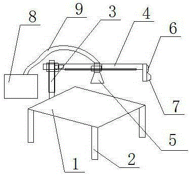
[0016] Combine figure 1 The illustrated dust removal device for a lathe includes a lathe 1 and a dust collector. A leg 2 is provided under the lathe 1, and the lathe 1 is fixed on the leg 2. The dust collector includes a bracket and a vacuum cleaner, and the bracket includes a bracket fixed on one side of the lathe The vertical column 3 and the supporting beam 4 set on the column 3, the suction nozzle 5 of the vacuum cleaner is set on the beam 4, the end of the beam 4 away from the column 3 is provided with a controller 6 and a handle 7, and the vacuum cleaner is controlled by 器6 Control.

[0017] In this embodiment, the body 8 of the vacuum cleaner is arranged around the lathe 1, and a dust suction pipe 9 is arranged between the body 8 and the dust suction nozzle 5.

[0018] In this embodiment, the column 3 is vertically arranged, and a lifting rack is arranged vertically on the column 3, and a lifting gear connected with the lifting rack is provided ...


PUM


Abstract

The invention discloses a lathe dedusting device which comprises a lathe and a dedusting device body. Support legs are arranged under the lathe which is fixed to the support legs. The dedusting device body comprises a support and a dust collector. The support comprises a stand column fixed to one side of the lathe and a support cross beam arranged on the stand column. A dust suction nozzle of the dust collector is arranged on the cross beam. A controller and a handle are arranged at the end, away from the stand column, of the cross beam. The dust collector is controlled by the controller. The lathe dedusting device has the advantages of being simple in structure, easy and convenient to use and good in dedusting effect.

Description

Technical field [0001] The invention relates to the field of lathes, in particular to a dust removal device for lathes. Background technique [0002] CNC lathes and turning centers are high-precision and high-efficiency automated machine tools. Equipped with a multi-station turret or power turret, the machine tool has a wide range of processing technology performance, and can process linear cylinders, oblique cylinders, arcs and various threads, grooves, worms and other complex workpieces, with linear interpolation, arcs Interpolate various compensation functions, and play a good economic effect in the mass production of complex parts. [0003] CNC lathes have basically occupied a dominant position in the current machining technology field. A considerable part of the existing CNC lathes use hollow spindles with hollow chucks. This structure is very convenient for processing long bars and can be programmed After continuous processing, a special feeder can be added outside the mach...

Claims


Application Information

Patent Timeline
IPC IPC(8): B23B25/00B08B15/00
CPCB23B25/00B08B15/00
Inventor 李孝良
Owner 湖南衡泰机械科技有限公司
Why Eureka
Try Eureka