Laser tin soldering machine

A soldering machine and laser technology, applied in welding equipment, welding/welding/cutting items, printed circuits, etc., can solve problems such as heating, unable to fix the point, accurately control energy output, and generate stress

Inactive Publication Date: 2017-03-08
KELUODE LASER EQUIP SHENZHEN +1
View PDF6 Cites 11 Cited by
  • Summary
  • Abstract
  • Description
  • Claims
  • Application Information

AI Technical Summary

Problems solved by technology

[0012] 1. Solve the problem that the entire workpiece (two welding objects) is heated to the welding temperature point during traditional welding, and change the large-area heating welding to the welding of extremely small points;
[0013] 2. Solve the problem that the energy output cannot be precisely controlled at a fixed point;
[0014] 3. Solve the problem of stress in the welding process;

Method used


Image

  • Laser tin soldering machine
  • Laser tin soldering machine

Examples


Embodiment Construction

[0031] In order to facilitate the understanding of the present invention, the present invention will be described in more detail below in conjunction with the accompanying drawings and specific embodiments. Preferred embodiments of the invention are shown in the accompanying drawings. However, the present invention can be implemented in many different forms and is not limited to the embodiments described in this specification. On the contrary, these embodiments are provided to make the understanding of the disclosure of the present invention more thorough and comprehensive.

[0032] It should be noted that when an element is referred to as being “fixed” to another element, it can be directly on the other element or there can also be an intervening element. When an element is referred to as being "connected to" another element, it can be directly connected to the other element or intervening elements may also be present. The terms "vertical", "horizontal", "left", "right" and...


PUM

PropertyMeasurementUnit
wavelengthaaaaaaaaaa
diameteraaaaaaaaaa

Abstract

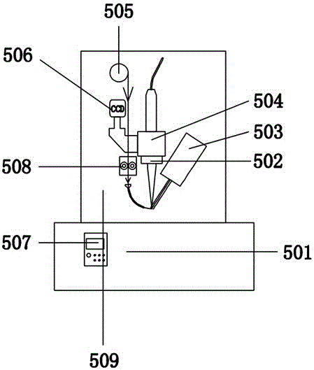
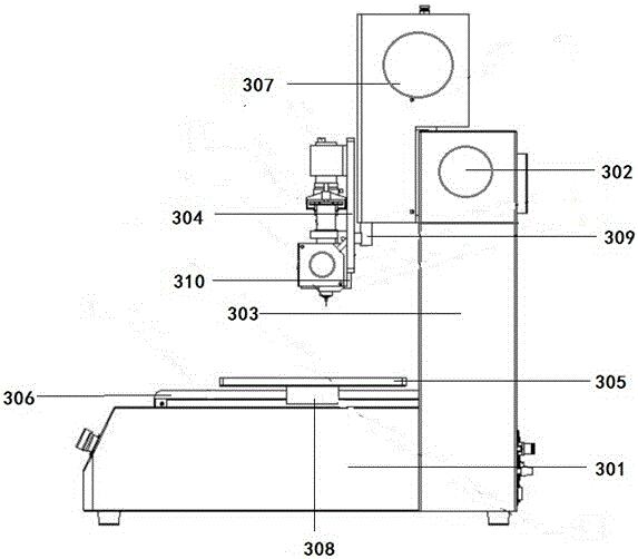
The invention provides a laser tin soldering machine which comprises a machine table body, a focusing mirror, a temperature inductor, a laser device, a soldering flux frame, a CCD monitor probe, a control device, a feeding device and a machining head fixing plate. The machining head fixing plate is arranged at the upper end of the machine table body. The laser device is arranged at the middle position of the machining head fixing plate. The CCD monitor probe is arranged on the left side of the fixing plate. The temperature inductor is arranged on the right side of the machining head fixing plate and is fixed in a bevel manner. The focusing mirror is arranged at the lower end of a laser. The soldering flux frame is arranged on the plane of the upper end of the left side of the machining head fixing plate. The feeding device is arranged at the lower end of the soldering flux frame. The control device is arranged at the upper end of the machine table body. According to the laser tin soldering machine, an electrical structure is used for control, solder wires, a triaxial working table, lasers are controlled, and therefore high precision and remote soldering are achieved, the service life is long, and the laser tin soldering machine is reasonable in design, simple in structure, reliable in operation and easy to operate.

Description

technical field [0001] The invention relates to the technical field of laser equipment, in particular to a laser soldering machine. Background technique [0002] Currently on the market, wave soldering, reflow soldering, immersion soldering, direct spot welding with ordinary welding guns and other methods are commonly used to solder circuit boards, wires, electronic devices, and microelectronics; [0003] Generally, welding is to heat circuit boards, wires, and electronic devices through high-temperature airflow, or high-temperature liquid, or high-temperature solid heat conductors for all workpieces or large-scale or individual individual heating (the minimum heating area is greater than 3 square millimeters), so that The nearby solder (including various tin materials or other metal powders) usually becomes fluid or liquid with the help of flux, which physically connects the pins, terminals and targets of electronic components, and forms adhesion welding after cooling. [...

Claims


Application Information

Patent Timeline
Patent Type & Authority Applications(China)
IPC IPC(8): B23K1/005B23K3/00B23K101/36B23K101/42
CPCB23K1/0056B23K1/0016B23K3/00
Inventor 胡柳平刘晨李艳飞黄再福朱宇军
Owner KELUODE LASER EQUIP SHENZHEN
Why Eureka
Try Eureka