Composite material structure, rubber sleeve manufacturing method, rubber sleeve, packer and bridge plug

A composite material and rubber cartridge technology, applied in the field of materials, can solve the problems affecting the long-term sealing effect of the rubber cylinder, unable to play a sealing role, and the rubber cylinder loses elasticity, etc., and achieves good high temperature resistance, reduced hardness, and easy compression. Effect

Inactive Publication Date: 2017-03-08
隆学武 +1
View PDF8 Cites 2 Cited by
  • Summary
  • Abstract
  • Description
  • Claims
  • Application Information

AI Technical Summary

Problems solved by technology

According to the inventor's test, when the first axial pressure was 30MPa, the inventor found that shoulders would appear in almost all rubber cartridges, and when the second axial pressure (such as 15MPa or 20MPa) was further applied, all the rubber cartridges would Can create splits at the shoulders, causing seal failure
[0009] Furthermore, the inventors have also found that even if the rubber cartridge can be temporarily sealed when the second axial pressure is applied, when bottomhole gas and other substances impact the rubber cartridge, the small molecules of high-temperature and high-pressure steam contained therein and the bottom-hole complex The gas will degrade the rubber cartridge of the polymer material, causing the rubber cartridge to lose its elasticity at the lower end first and fail to play a sealing role, and then degrade and lose its elasticity in the middle part of the rubber cartridge, affecting the long-term sealing effect of the rubber cartridge sex

Method used


Image

  • Composite material structure, rubber sleeve manufacturing method, rubber sleeve, packer and bridge plug
  • Composite material structure, rubber sleeve manufacturing method, rubber sleeve, packer and bridge plug
  • Composite material structure, rubber sleeve manufacturing method, rubber sleeve, packer and bridge plug

Examples


Embodiment Construction

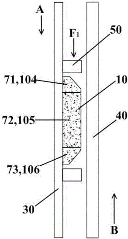
[0058] The directions "up" and "down" described below are based on figure 2 described as a reference.

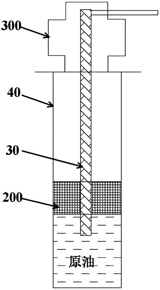
[0059] like figure 1 The compression packer 200 is shown with the cartridge 10 of the present application. The compression packer 200 is connected to the base pipe 30 and placed in the casing 40 . The compression packer 200 needs to separate different oil layers and water layers in the wellbore and withstand a certain pressure difference. Get out smoothly.

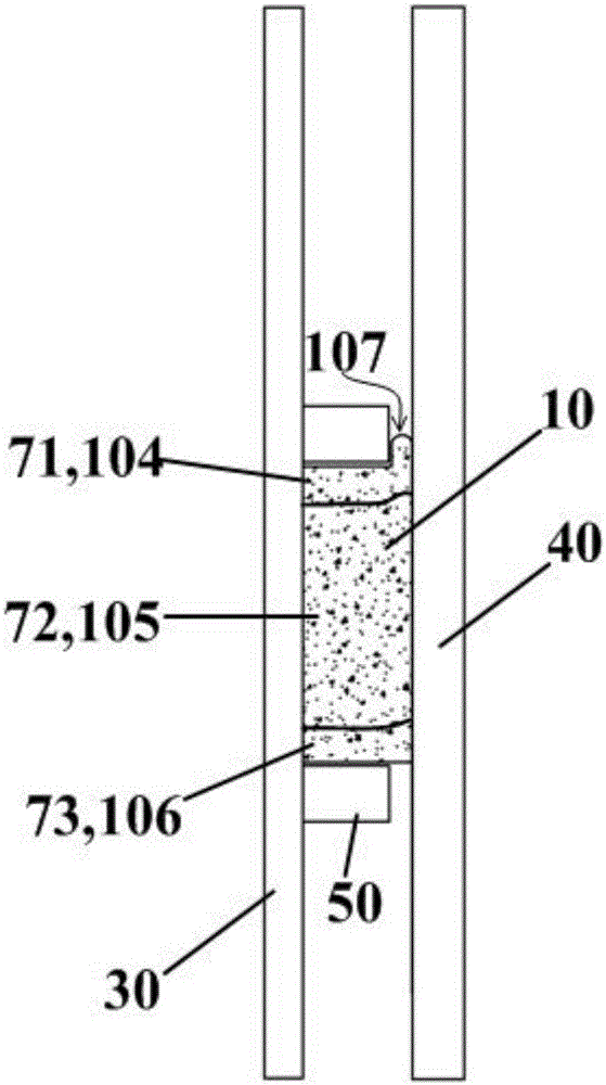
[0060] like figure 2 As shown, the rubber cartridge 10 is located in the annular space formed by the sleeve 40 and the central tube 30, and the rigid spacer ring 50 provides the first axial pressure F from top to bottom (ie, the first axial direction A) in the axial direction. 1 , in other embodiments, the rigid spacer ring 50 can also be removed and the first axial pressure F can be applied to the rubber cartridge 10 1 other components instead. like figure 2 As shown, the two ends of the rubber cartridge 10 a...


PUM

PropertyMeasurementUnit
thicknessaaaaaaaaaa
thicknessaaaaaaaaaa
thicknessaaaaaaaaaa

Abstract

The invention relates to the field of materials, and particularly relates to a high-temperature-resistance and high-pressure-resistance composite material structure, a rubber sleeve manufactured by using the composite material structure, a rubber sleeve manufacturing method, a packer with the rubber sleeve and a bridge plug. The composite material structure is woven by graphite and metal wire mixture and high-temperature-resistance fibers, wherein the graphite and metal wire mixture comprises continuous metal wires and graphite seals, and the metal wires are inserted into the graphite seals or wound on the surfaces of the graphite seals. According to the composite material structure, the metal wires are inserted into the graphite seals or wound on the surfaces of the graphite seals, so that deformation of the graphite seals can be restrained, and the graphite and metal wire mixture can be prevented from being cracked during axial pressure action; and the metal wires and graphite seals have high temperature resistance, so that the graphite and metal wire mixture has excellent high temperature resistance. When the graphite and metal wire mixture and the high-temperature-resistance fibers are woven to form the composite material structure, the hardness of the composite material structure can be effectively reduced, and the composite material structure can be easily compressed.

Description

technical field [0001] The present application relates to the field of materials, in particular to a composite material structure resistant to high temperature and high pressure, a rubber cartridge manufactured using the composite material structure, a manufacturing method of the rubber cartridge, a packer and a bridge plug with the rubber cartridge. Background technique [0002] The recoverable heavy oil in the world is about 400 billion tons, about 2.5 times that of conventional crude oil. The colloid and bitumen content in the heavy oil is relatively high, and the light distillate is less, so the relative density and viscosity are relatively high. Viscosity is the main factor affecting the recovery of heavy oil. As the temperature increases, the viscosity decreases quickly, which is beneficial to the improvement of heavy oil recovery. Steam huff and puff technology is the main technology for heavy oil recovery. This technology injects high-temperature and high-pressure s...

Claims


Application Information

Patent Timeline
Patent Type & Authority Applications(China)
IPC IPC(8): E21B33/127E21B33/134D04C1/02D04C1/06
CPCE21B33/127D04C1/02D04C1/06D10B2101/20E21B33/134
Inventor 宋炜隆学武
Owner 隆学武
Why Eureka
Try Eureka