Arrangement method of catalytic cracking tetra-cyclone separator

A cyclone separator, catalytic cracking technology, applied in separation methods, chemical instruments and methods, dispersed particle separation, etc., can solve the problem of insufficient utilization of the sedimentation separation function in the dilute phase space, increase the working load of the quadruple cyclone, and the concentration of particles at the entrance of the quadruple cyclone advanced questions

Inactive Publication Date: 2017-03-15
CHINA UNIV OF PETROLEUM (BEIJING)
View PDF5 Cites 5 Cited by
  • Summary
  • Abstract
  • Description
  • Claims
  • Application Information

AI Technical Summary

Problems solved by technology

This improved structure solves the problem of gas blow-by of the quadrotor to a certain extent, but there are still problems such as the high concentration of particles at the inlet of th...

Method used


Image

  • Arrangement method of catalytic cracking tetra-cyclone separator
  • Arrangement method of catalytic cracking tetra-cyclone separator
  • Arrangement method of catalytic cracking tetra-cyclone separator

Examples


Embodiment 1

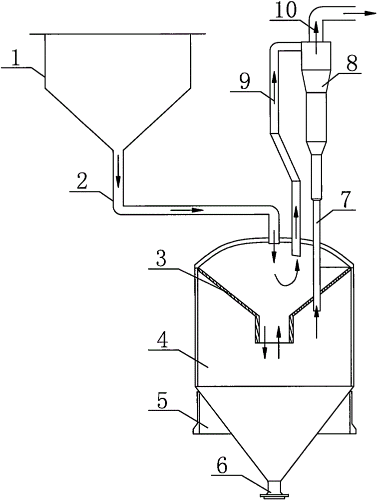
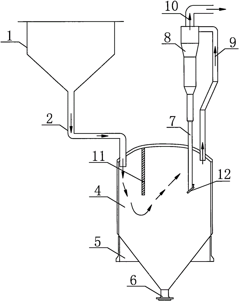
[0020] figure 2 A typical structure type of the novel four-spin system proposed by the present invention is given, and figure 1 The difference of the traditional four-rotation system shown is that in this structure, the conical baffle (3) inside the storage tank (4) of the traditional four-rotation system is removed, and the upper part of the storage tank (4) is set up A vertical partition (11). Here, with the storage tank (4) top, the space on the left side of the vertical partition (11) is defined as an inertial separation zone; with the storage tank (4) top, the space on the right side of the vertical partition (11) is defined as Sedimentation separation zone. The outlet of the three-rotation discharge pipe (2) is arranged on the side farther away from the vertical partition (1) and close to the wall of the storage tank (4). Due to the high air velocity in the three-rotation discharge pipe (2), after entering the inertial separation space on the left, due to the sudden ...

Embodiment 2

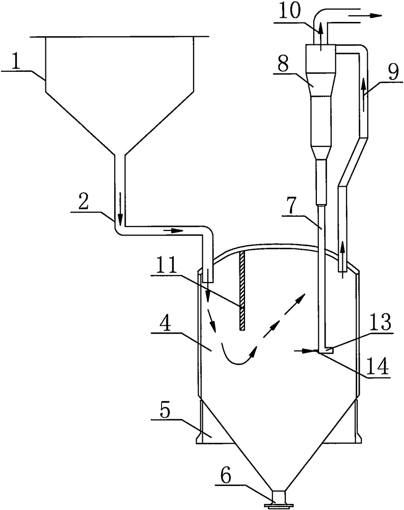
[0023] image 3 Another typical structure type of the new four-spin system proposed by the present invention is given, which is generally the same as figure 2 The structure type shown is the same, the difference is that an L-shaped valve (13) is set at the bottom of the four-rotary material leg (7), which is a common non-mechanical material leg air lock mechanism. Similarly, other similar Non-mechanical dipleg air locks, such as V-valves, can also be used here. In order to ensure the normal operation of this type of non-mechanical valve, it is necessary to arrange a loosening air duct (14) on this type of non-mechanical valve, and to ensure the smooth discharge of particles and the normal air-locking function by inputting a continuous loosening air flow.

Embodiment 3

[0025] Figure 4 Another typical structure type of the new four-spin system proposed by the present invention is given, which is generally the same as image 3 The structural types shown are the same, the difference is that a layer of louver grille (15) is arranged at the bottom of the storage tank (4), and this layer of grille (15) is arranged on the highest possible material layer at the bottom of the storage tank (4). Above the position, 0.05-0.5m away from the surface of the highest possible material layer. Figure 5A partial cross-sectional schematic diagram of the louver grille (15) is given. It is precisely because of the function of its inclined blades (16) that it can perform the function of inertial separation of some particles without affecting the circulation of the gas, so as to further reduce the gas flow rate. The eluting entrainment effect on the separated solid particle material layer at the bottom of the storage tank (4). In addition to the louver grille (1...


PUM


Abstract

The invention discloses an arrangement method of a catalytic cracking tetra-cyclone separator (referred to as a tetra-cyclone). The tetra-cyclone separator system mainly comprises a tertiary cyclone discharge pipe, a material storage tank, a tetra-cyclone gas inlet pipe and a tetra-cyclone. A dilute phase space at the upper part of the material storage tank is provided with a vertical partition plate. The vertical partition plate divides the dilute phase space of the material storage tank into an inertial separation zone and a sedimentation separation zone. Dust-containing flue gas in the tertiary cyclone discharge pipe is introduced from the top of the inertial separation zone, passes through the inertial separation zone and the sedimentation separation zone and then enters the tetra-cyclone through the tetra-cyclone gas inlet pipe at the top of the sedimentation separation zone. Gas subjected to dedusting in the tetra-cyclone enters a downstream critical nozzle. Solid particles separated by the tetra-cyclone enter a bottom material layer of the material storage tank along a dipleg. The inertial separation zone realizes gas and solid separation through difference of gas and solid particles. The sedimentation separation zone realizes gas-solid separation by a lower section gas velocity. Through the above two kinds of particle pre-separation measures, a particle concentration at the inlet of the tetra-cyclone and separation load are reduced. A gas-locking device is arranged at a tetra-cyclone dipleg particle outlet so that backflow of gas in the dipleg is prevented and smooth delivery of particles in the dipleg is guaranteed.

Description

technical field [0001] The invention relates to an arrangement mode of a fourth-stage cyclone separator for catalytic cracking, and belongs to the technical field of petrochemical industry. Background technique [0002] In the catalytic cracking unit of the refinery, the third-stage cyclone separator (hereinafter referred to as the three-cyclone) is an important equipment for the separation and recovery of high-temperature flue gas catalyst particles in the regenerator, and it is also to ensure the long-term operation of the smoke machine and avoid the erosion and wear of the catalyst particles. The key equipment of the blade. In the three-rotation system, in order to make it have a higher particle collection efficiency, a critical nozzle is often provided to control a small amount of flue gas (3-5%) to be drawn from the three-rotation ash hopper, and the fine particles separated by the three-rotation The particulate catalyst enters the storage tank together with this part ...

Claims


Application Information

Patent Timeline
IPC IPC(8): B01D50/00B01D45/12
Inventor 刘对平张永民李希斌柯桥鲁润润魏庆
Owner CHINA UNIV OF PETROLEUM (BEIJING)
Why Eureka
Try Eureka