Capillary tube blanking pier protrusion forming machine

A technology for capillary tubes and forming machines, applied in other manufacturing equipment/tools, heat exchange equipment, manufacturing tools, etc., to achieve the effects of high equipment automation, high safety performance, and high production efficiency

Inactive Publication Date: 2017-03-15
合肥瑞登机械设备有限公司
View PDF8 Cites 0 Cited by
  • Summary
  • Abstract
  • Description
  • Claims
  • Application Information

AI Technical Summary

Problems solved by technology

The capillary is used for the throttling function because its inner diameter is very small (about 1-1.5mm), and some will be thinner. Due to its small inner diameter, the capillary cannot be punched with concave and convex points on its surface to achieve insertion during welding. Depth limit, the method of limiting the capillary port in the prior art is to increase the boss. The conventional method is to manually take the capillary and process it on the stamping equipment. If there are bosses at both ends, then perform two stampings

Method used


Image

  • Capillary tube blanking pier protrusion forming machine
  • Capillary tube blanking pier protrusion forming machine
  • Capillary tube blanking pier protrusion forming machine

Examples


Embodiment Construction

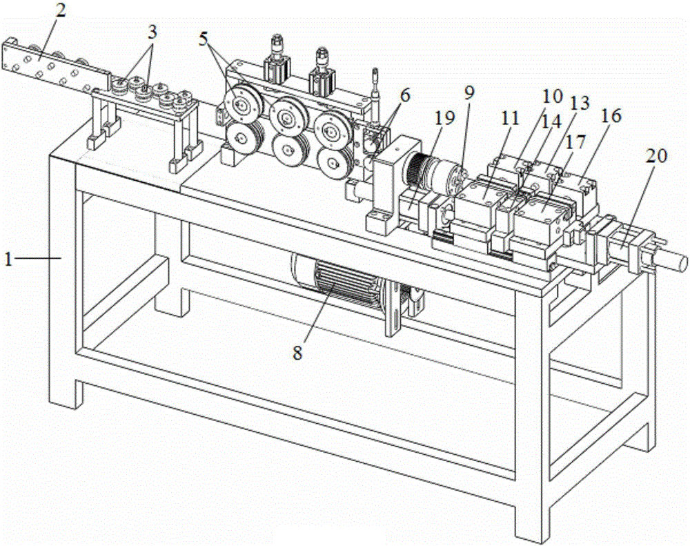
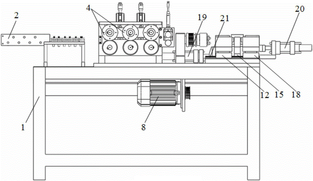
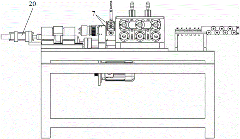
[0015] See attached Figure 1-7 As shown, the capillary tube blanking pier convex molding machine includes a frame 1 and a straightening mechanism, a feeding mechanism, a guide counting mechanism, a chipless cutting mechanism, a pier convex forming mechanism, and a control system provided on the frame 1. The straightening mechanism is composed of a straightening wheel 2 mounted on a straightening plate 3; the feeding mechanism is formed by a stepping motor 4 that is symmetrical up and down driving a transfer wheel 5 connected to it and engaged with each other; the guide counting The mechanism is composed of a guide wheel 6 that matches up and down, and the guide wheel 6 is connected to the encoder 7; the chipless cutting mechanism is composed of a motor 8 driving a cutter head 9 through a timing belt wheel; The mechanism includes a first hydraulic cylinder 10, a first clamping mold 11, a first slider 12, a second hydraulic cylinder 13, a second clamping mold 14, a second fixing...


PUM


Abstract

The invention relates to capillary tube machining equipment, in particular to a capillary tube blanking pier protrusion forming machine. The capillary tube blanking pier protrusion forming machine comprises a rack, an alignment mechanism, a feeding mechanism, a guiding and counting mechanism, a chipless cutting mechanism, a pier protrusion forming mechanism and a control system, wherein the alignment mechanism, the feeding mechanism, the guiding and counting mechanism, the chipless cutting mechanism, the pier protrusion forming mechanism and the control system are arranged on the rack. The alignment mechanism is formed in a manner that alignment wheels are installed on an alignment plate; the feeding mechanism is formed in a manner that stepping motors drive delivery wheels; the guiding and counting mechanism is composed of guide wheels; the chipless cutting mechanism is formed in a manner that a motor drives a chipper disc by means of a synchronous pulley; the pier protrusion forming mechanism comprises a first hydraulic cylinder, a first clamping die, a first sliding block, a second hydraulic cylinder, a second clamping die, a second fixing seat, a third hydraulic cylinder, a third clamping die, a third sliding block, a fifth hydraulic cylinder, a sixth hydraulic cylinder and a linear sliding rail. According to the capillary tube blanking pier protrusion forming machine, work of all the hydraulic cylinders is precisely controlled through a PLC, pier protrusion forming conducted on one end or two ends of a capillary tube can be completed in the blanking process of the capillary tube, the equipment automation degree is high, and safety performance is high.

Description

Technical field [0001] The invention relates to capillary processing equipment, in particular to a capillary tube blanking and convex forming machine. Background technique [0002] Due to the requirements of the scale of production, the current production capacity of domestic electrical appliance manufacturers urgently needs to be continuously improved, and the product quality requirements are also continuously improved to reduce production costs. Relying solely on expanding the production site and increasing the number of assembly lines not only increases the cost, but also requires sufficient time to achieve. How to achieve the goal of improving production efficiency and reducing costs on the existing basis is an urgent problem for manufacturers. In the refrigeration industry, especially in the refrigerator and air-conditioning industries, capillary tubes are mostly used in throttling systems; during refrigeration, the capillary tube throts the high-pressure liquid refrigerant...

Claims


Application Information

Patent Timeline
IPC IPC(8): B21D53/02B21D19/08B23P23/04
CPCB21D19/08B21D53/02B23P23/04
Inventor 黄茂刚
Owner 合肥瑞登机械设备有限公司
Why Eureka
Try Eureka