
Pogo pin mold, machining process thereof and pogo pin assembly process

A processing technology and probe technology, applied in the field of pogopin probe needle molds, can solve the problems of low assembly efficiency, easy dislocation between plates and difficult fixing, etc. The effect of efficiency

Pending Publication Date: 2017-03-15
苏州润弘安创自动化科技有限公司
View PDF9 Cites 2 Cited by
  • Summary
  • Abstract
  • Description
  • Claims
  • Application Information

AI Technical Summary

Problems solved by technology

However, in the needle mold provided by this patent, the needle plate (3) is formed by superimposing the upper needle plate 31, the base plate 32 and the lower needle plate 33. This three-layer structure is difficult to fix during processing, and the gap between the plates is easy. Misalignment occurs, and the processing error is difficult to control, which reduces the subsequent assembly accuracy of the probe and lowers the assembly efficiency.

Method used


Image

  • Pogo pin mold, machining process thereof and pogo pin assembly process
  • Pogo pin mold, machining process thereof and pogo pin assembly process
  • Pogo pin mold, machining process thereof and pogo pin assembly process

Examples


Embodiment Construction

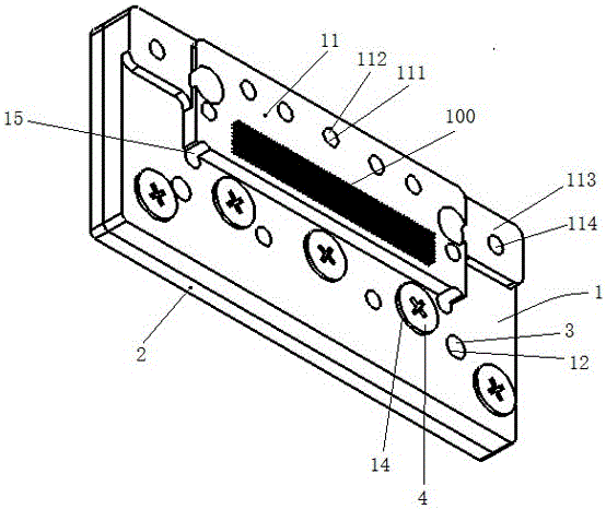
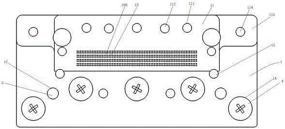
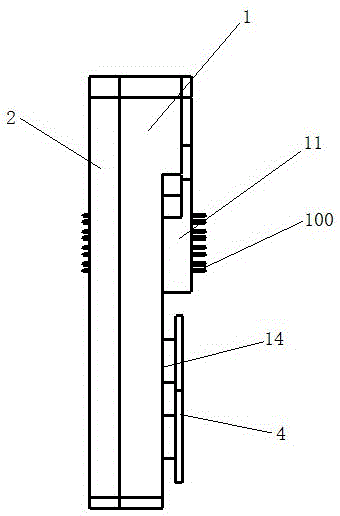
[0037] see Figure 1~Figure 4 , a pogopin probe needle mold according to the present invention, the needle mold includes: a lower cover plate 1, a square boss 11 is protruded on one side of the surface, and several lower plates are provided on the other side along the length direction of the lower cover plate 1. Through holes 12, one side of the boss 11 is provided with a number of lower pinholes 13 along the thickness direction of the boss 11 for the pogopin probe 100 to pass through; The upper pinhole (not shown) and the upper through hole (not shown) corresponding to the lower pinhole 13 and the lower through hole 12 respectively; The connection between the upper cover plate 2 and the lower cover plate 1 is formed by passing the fixing member 3 through the upper and lower through holes; the Pogopin probe 100 passes through the upper pinhole 13 of the lower cover plate 1 through the upper pinhole of the upper cover plate 2 .

[0038]Further, in one embodiment of the presen...


PUM


Abstract

The invention provides a pogo pin mold, a machining process thereof and a pogo pin assembly process. The pin mold comprises a lower cover plate and an upper cover plate, wherein a square lug boss protrudes from one side of the surface of the lower cover plate; the other side of the surface of the lower cover plate is provided with a plurality of lower through holes along the length direction of the lower cover plate; along the thickness direction of the lug boss, one side of the lug boss is provided with a plurality of lower pinholes for the pogo pin to pass through; corresponding to the lower cover plate, the upper cover plate is provided with upper pinholes and upper through holes in the surface of the upper cover plate, wherein the upper pinholes correspond to the lower pinholes, and the upper through holes correspond to the lower through holes; the upper cover plate adheres to the other surface, provided with the lug boss, of the lower cover plate; a fixing part passes through the upper and lower through holes to realize connection between the upper cover plate and the lower cover plate; and the pogo pin penetrates out of the upper pinholes of the upper cover plate from the lower pinholes of the lower cover plate. The machining process of the pin mold is optimized, and errors generated in a machining process are reduced to improve the machining precision; by adopting a more reasonable high-precision assembly process, the work efficiency of assembly is improved; and the pin mold is simple in structure, low in production cost and good in economic benefits.

Description

technical field [0001] The invention relates to a pogopin probe needle mold, its processing technology and probe assembly technology. Background technique [0002] Pogo pin is a precision connector used in electronic products such as mobile phones, and is widely used in semiconductor equipment for connection. [0003] Pogo pin is a spring-type probe formed by riveting and pre-pressing the three basic parts of needle shaft, spring and needle tube through precision instruments. There is a precise spring structure inside. The surface coating of the pogo pin is generally gold-plated, which can better improve its anti-corrosion function, mechanical properties, electrical properties, etc. Needle points include pointed needles, grasping needles, round needles, knife-shaped needles, etc. Pogo pins are generally used in precision connections in electronic products such as mobile phones, communications, automobiles, medical, aerospace, etc., which can improve the corrosion resistanc...

Claims


Application Information

Patent Timeline
Patent Type & Authority Applications(China)
IPC IPC(8): B23P15/00G01R1/073
CPCG01R1/07307B23P15/00
Inventor 徐文飞王东永潘伟仁王勤生顾凯
Owner 苏州润弘安创自动化科技有限公司
Learn More