Uniformly-stressing tightening device

An elastic device and uniform force technology, applied in metal processing and other directions, can solve the problems of affecting work efficiency, different tightness, poor turning effect, etc., and achieve the effect of improving work efficiency, beautiful appearance and good turning effect.

Inactive Publication Date: 2017-03-15
新昌县儒岙镇衡翔机械厂
View PDF0 Cites 0 Cited by
  • Summary
  • Abstract
  • Description
  • Claims
  • Application Information

AI Technical Summary

Problems solved by technology

[0004] The purpose of the present invention is to overcome the shortcomings of time-consuming and labor-intensive work that affects work efficiency due to the different tightness of each jaw when the workpiece is manually fixed with a T-shaped bar. The technical problem is to provide an evenly stressed elastic device

Method used


Image

  • Uniformly-stressing tightening device
  • Uniformly-stressing tightening device

Examples


Embodiment 1

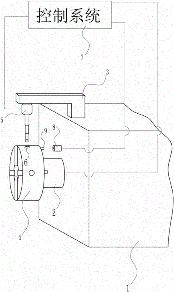
[0015] A uniformly stressed elastic device, such as Figure 1-2 As shown, it includes a lathe headstock 1, a rotating shaft 2, a crossbeam 3, a chuck 4, an elastic device 5, a wrench insertion hole 6 and a control system 7, and the front part of the lathe headstock 1 is provided with a rotating shaft 2, and the lathe headstock 1 A crossbeam 3 is provided above the top of the crossbeam 4, and the chuck 4 is installed on the rotating shaft 2. An elastic device 5 is provided under the front end of the crossbeam 3. Four wrench insertion holes 6 are evenly spaced on the outer wall of the chuck 4. The rotating shaft 2 and the elastic The device 5 is connected with the control system 7 respectively; the elastic device 5 includes an electric wrench 51, a lifting motor 52, a lifting rod 53, a groove 54 and a straight hexagonal wrench 55, and one end of the electric wrench 51 is connected to the beam 3, and the other side is connected to the lifting wrench. The motor 52 is connected, an...


PUM


Abstract

The invention discloses a uniformly-stressing tightening device. The tightening device comprises a lathe headstock, a rotating shaft, a cross beam, a chuck, a tightening device body, winch inserting holes and a control system. The rotating shaft is arranged at the front part of the lathe headstock. The cross beam is arranged above the lathe headstock. The chuck is mounted on the rotating shaft. The tightening device body is arranged below the front end of the cross beam. The four wrench inserting holes are uniformly formed in the outer wall of the chuck in a spaced manner. The rotating shaft and the tightening device body are separately connected with the control system. The tightening device body comprises an electric wrench, a lifting motor, a lifting rod, a groove and a straight hexagon wrench. One end of the electric wrench is connected to the cross beam. Through adoption of the tightening device, the degrees of tightness of clamping jaws in fixing can be the same, the turning effect is good, time and labor are saved, and the working efficiency is improved.

Description

technical field [0001] The invention relates to a machine tool, in particular to a uniformly stressed elastic device. Background technique [0002] A chuck is a mechanical device used to clamp a workpiece on a machine tool. A machine tool accessory that clamps and positions workpieces by using the radial movement of movable jaws evenly distributed on the chuck body. The chuck is generally composed of three parts: the chuck body, the movable jaw and the jaw driving mechanism. The minimum diameter of the chuck body is 65mm, and the maximum can reach 1500mm. There is a through hole in the center to pass the workpiece or bar; the back has a cylindrical or short tapered structure, which is connected directly or through the flange to the end of the machine tool spindle. . Chucks are usually installed on lathes, cylindrical grinders and internal grinders, and can also be used with various indexing devices for milling machines and drilling machines. [0003] When the existing ch...

Claims


Application Information

Patent Timeline
Patent Type & Authority Applications(China)
IPC IPC(8): B23Q5/58
CPCB23Q5/585
Inventor 王敏
Owner 新昌县儒岙镇衡翔机械厂
Why Eureka
Try Eureka