Ceramic grouting forming production line and production technique

A production line and grouting technology, used in ceramic molding machines, ceramic molding workshops, manufacturing tools, etc., can solve the problems of high labor intensity and low production efficiency, and achieve the goal of improving production efficiency, saving time, saving quantity and occupying space. Effect

Active Publication Date: 2017-03-15
ZHIXINLONG TECH (GUANGDONG) CO LTD
View PDF5 Cites 8 Cited by
  • Summary
  • Abstract
  • Description
  • Claims
  • Application Information

AI Technical Summary

Problems solved by technology

The production process requires a lot of space to place the plaster mold after grouting or dem

Method used


Image

  • Ceramic grouting forming production line and production technique
  • Ceramic grouting forming production line and production technique

Examples


Embodiment Construction

[0025] In order to make the object, technical solution and effect of the present invention more clear and definite, the following examples are given to further describe the present invention in detail. It should be understood that the specific embodiments described here are only used to explain the present invention, not to limit the present invention.

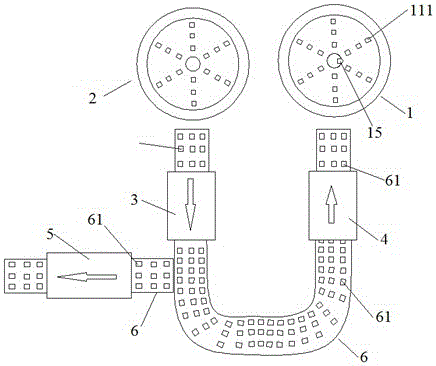
[0026] Such as figure 1 As shown, this embodiment relates to a ceramic grouting forming production line, including a grouting workbench 1 for grouting into a plaster mold, and a grouting workbench 2 for pouring out excess mud in a plaster mold. For drying the first drying chamber 3 with the mud layer plaster mold, the second drying chamber 4 for drying the plaster mold and the third drying 5 for drying the plaster mold, the first drying chamber 3, the second drying chamber Both the drying chamber 4 and the third drying chamber 5 are provided with a transfer device 6 with a plurality of transfer stations 61, the input end of t...


PUM


Abstract

The invention discloses a ceramic grouting forming production line. The ceramic grouting forming production line comprises a grouting workbench, a pouring workbench, a first drying chamber, a second drying chamber and a third drying chamber, wherein the grouting workbench is used for injecting grout into a plaster mold, the pouring workbench is used for pouring out redundant grout in the plaster mold, the first drying chamber is used for drying the plaster mold with a blank mud layer, the second drying chamber is used for drying the plaster mold, and the third drying chamber is used for drying a blank body; and the first drying chamber, the second drying chamber and the third drying chamber are each provide with a conveying device with a plurality of conveying stations; the input end of the first drying chamber is close to the pouring workbench, the input ends of the second drying chamber and the third drying chamber are connected with or close to the output end of the first drying chamber, and the output end of the second drying chamber is close to the grouting workbench. By installing the three drying chambers and the conveying devices, procedures such as grouting, pouring, drying and demolding can be conducted simultaneously, and time is greatly saved; and meanwhile, the plaster mold is recycled continuously in the whole process, a large space for placing the idle plaster mold is not needed, the number of plaster molds is reduced, and the spaced occupied by the plaster mold is reduced.

Description

technical field [0001] The invention relates to a ceramic grouting forming production line and a production process. Background technique [0002] Grouting molding is to use the water absorption of the plaster mold to inject fluid mud into the plaster mould, so that the mud adheres to the model in a dispersed manner, forming a mud layer with the same shape as the model, and gradually increases with time. When it reaches a certain thickness, it will be separated from the mold wall by drying and shrinkage, and then it will be demoulded and taken out to form a green body. All products with complex shapes, irregular or thin tires can be produced by grouting molding. Therefore, grouting molding is widely used in the fields of daily ceramics, industrial art porcelain, sanitary ware porcelain and modern ceramics. [0003] In the existing grouting forming process, generally, grouting is first injected into a batch of dried plaster molds, and after standing for a few minutes, the ex...

Claims


Application Information

Patent Timeline
IPC IPC(8): B28B15/00B28B17/00B28B1/26B28B13/02
CPCB28B1/26B28B13/021B28B15/00B28B17/0081
Inventor 甄活强
Owner ZHIXINLONG TECH (GUANGDONG) CO LTD
Why Eureka
Try Eureka