An air pressure control method and device used for photonic band gap optical fiber drawing

A gas pressure control, photonic band gap technology, applied in the field of optical fiber manufacturing, can solve the problems of volume, weight, power consumption and cost increase, and achieve the effect of stable gas pressure and improved accuracy

Active Publication Date: 2017-03-15
BEIHANG UNIV
View PDF6 Cites 11 Cited by
  • Summary
  • Abstract
  • Description
  • Claims
  • Application Information

AI Technical Summary

Problems solved by technology

Although these measures can improve the environmental adaptability of fiber optic gyroscopes to a certain extent, they also bring some side effects, such as increased volume, weight, power consumption and cost.

Method used


Image

  • An air pressure control method and device used for photonic band gap optical fiber drawing
  • An air pressure control method and device used for photonic band gap optical fiber drawing
  • An air pressure control method and device used for photonic band gap optical fiber drawing

Examples


Embodiment Construction

[0036] The present invention will be further described in detail below in conjunction with the accompanying drawings.

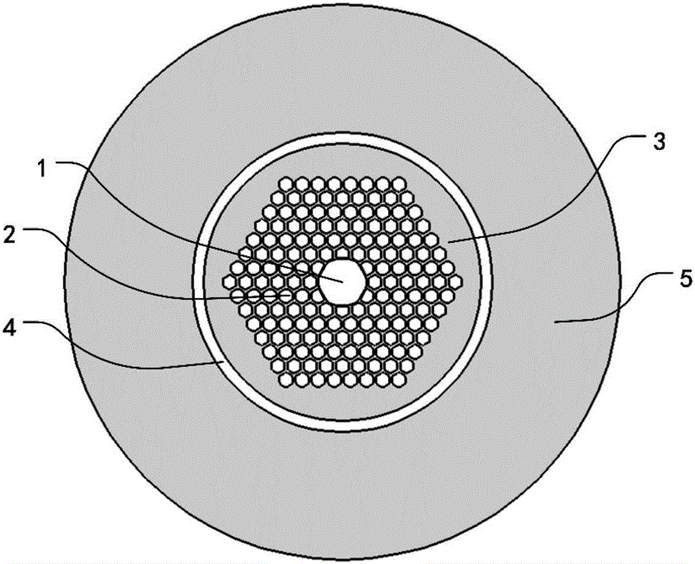
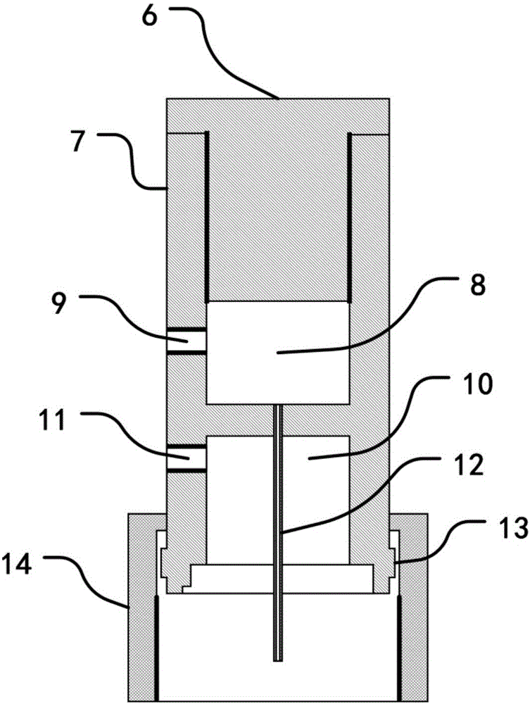
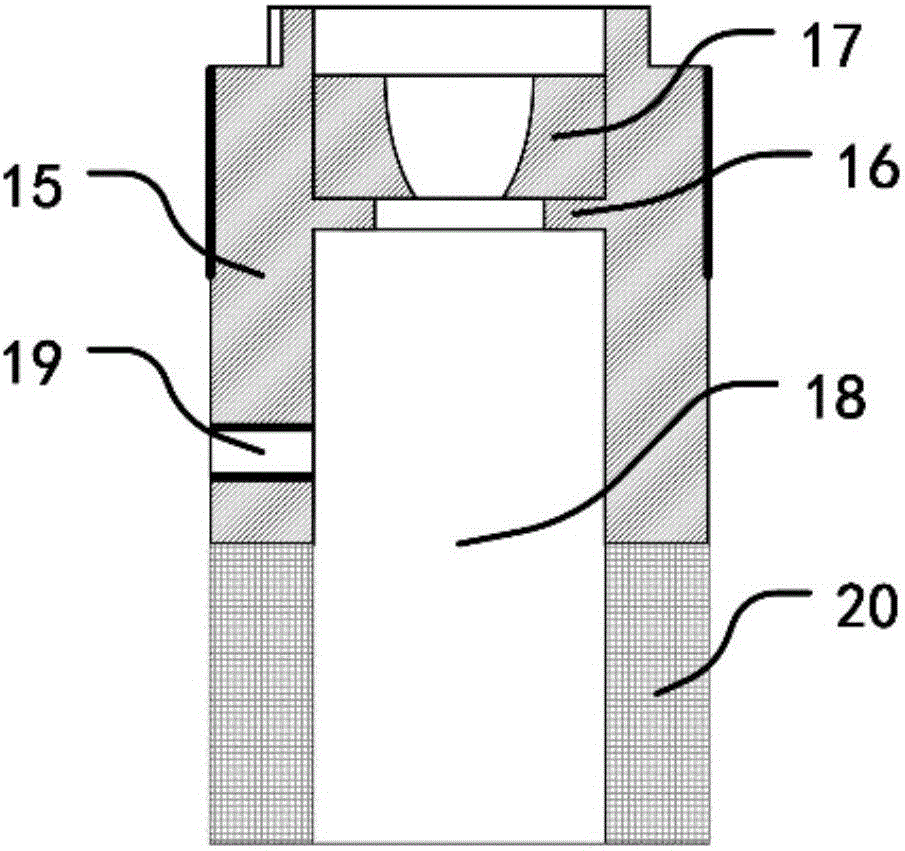
[0037] The present invention firstly provides an air pressure control device applied to the drawing of photonic bandgap optical fibers, Figure 2 ~ Figure 4 The structures shown correspond to the first part, the second part and the third part of the air pressure control device respectively, wherein the first part and the second part are assembled as the optical fiber air pressure control fixture 28, which are mainly used to clamp the intermediate body 3 and place the The air pressure partition, the third part is the air pressure control electrical part, which has the air pressure control function. Such as figure 1As shown, the second step of the photonic bandgap fiber drawing process is mainly to insert the intermediate body 3 drawn in the first step into the quartz sleeve 5 and draw it into a photonic bandgap fiber. There are three regions that need to be c...


PUM


Abstract

The invention discloses an air pressure control method and device used for photonic band gap optical fiber drawing, and belongs to the technical field of optical fiber manufacturing. The method includes firstly inserting an intermediate into an intermediate fixing table, sealing the intermediate and the intermediate fixing table with sealing glue, connecting a single-cavity body and a double-cavity body in a threaded manner, with a fiber core duct being inserted into an intermediate fiber core during connection, and after assembling is finished, communicating a fiber-core-cavity gas pipe port, a cladding-cavity gas pipe port and an outer-cavity gas pipe port to a gas chamber of an air pressure control electric part through gas guiding pipes separately to achieve independent air pressure control of three regions which are a fiber core cavity, a cladding cavity and an outer cavity. The method and the device overcome a problem of independent precise air pressure control of the three regions during a photonic band gap optical fiber drawing process. The method and the device have universality and are suitable for porous micro-structured optical fiber drawing requiring independent air pressure control for separated regions. A pressure difference is adopted to determine on-off control time of an electromagnetic valve, thus controlling a gas flux through the pressure difference and increasing air pressure control precision.

Description

technical field [0001] The invention relates to an air pressure control method and device used in drawing photonic bandgap optical fibers, and belongs to the technical field of optical fiber manufacturing. Background technique [0002] As a new type of microstructured fiber, photonic bandgap fiber is suitable for optical fiber sensing, high-power lasers, and optical fiber communication. The light inside cannot be transmitted in the cladding honeycomb structure, so that the light wave is limited to the air core in the middle. Compared with silica, the physical and chemical properties of air are more stable, so photonic bandgap fibers have better environmental adaptability than traditional fibers, such as sensitivity to environmental factors such as temperature, electromagnetic field, and space radiation Low, insensitive to bending, etc., it is extremely suitable for optical fiber sensing and signal transmission in complex environments. [0003] With the deepening of researc...

Claims


Application Information

Patent Timeline
Patent Type & Authority Applications(China)
IPC IPC(8): C03B37/03C03B37/025
CPCC03B37/0253C03B37/03
Inventor 徐小斌高福宇宋凝芳金靖张春熹张智昊
Owner BEIHANG UNIV
Why Eureka
Try Eureka