Recycled aggregate pretreatment equipment

A technology for recycled aggregates and pretreatment, applied in sustainable waste treatment, solid waste management, climate sustainability, etc. Improve quality, reduce impact, and achieve the effect of recycling

Active Publication Date: 2017-03-15
XIAMEN TIANRUN JINLONG BUILDING MATERIAL
7 Cites 13 Cited by

AI-Extracted Technical Summary

Problems solved by technology

However, due to its own shortcomings, such as large water absorption, high fine powder content, high porosity, large crushing index, low density, etc., if recycled aggregate is directly applied to concrete, it will lead to poor workability and collapse of freshly mixed recycled aggregate. Large sag loss, low strength and poor durability after hardening, which greatly limit its application range
Many recycled aggregate strengthening methods have been published. Studies have shown that these strengthening methods can greatly improve the performance of recycled aggregates, thereby im...

Abstract

The invention discloses recycled aggregate pretreatment equipment. The recycled aggregate pretreatment equipment comprises a pretreatment system, a spraying system and a liquid supply system. The pretreatment system comprises a wetting box, a rolling net drum horizontally arranged in the wetting box in the axial direction, a driving part for driving the rolling net drum to rotate, a receiving bin, and a storage yard, wherein a feeding channel is formed in one end, in the axial direction, of the wetting box, a discharging channel is formed in the other end, in the axial direction, of the wetting box and connected with the receiving bin, and a spiral blade used for guiding recycled aggregate from one end of the rolling net drum to the other end is arranged in the rolling net drum. The spraying system is arranged above the storage yard and used for conducting spraying on recycled aggregate in the storage yard. The liquid supply system is used for providing liquid sources for the wetting box and the spraying system respectively. The recycled aggregate is uniformly pre-wetted through rotating and screening of the rolling net drum, and meanwhile small particles not meeting the particle size requirement, surface-adhering micropowder, impurities and the like in the recycled aggregate are removed; the spraying system conducts spraying on the recycled aggregate in the storage yard, and it is guaranteed that the pretreated recycled aggregate in a surface-wetted state without clear liquid so that the storage quality of the pretreated recycled aggregate can be guaranteed.

Application Domain

Technology Topic

Image

  • Recycled aggregate pretreatment equipment

Examples

  • Experimental program(1)

Example Embodiment

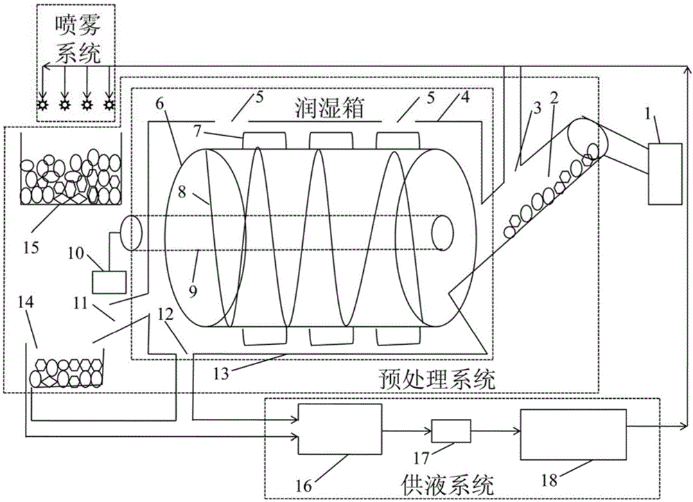
[0028] Please refer to figure 1 , A pretreatment equipment for recycled aggregates of the present invention includes a pretreatment system, a spray system, and a liquid supply system. The pretreatment system is used to process the recycled aggregate, remove the small particles that do not meet the particle size requirements, the surface-attached micropowder, sundries, etc., so that the recycled aggregate can absorb a certain amount of water or strengthen liquid. The spray system is used to keep the surface of the recycled aggregate treated by the pretreatment system moist. The liquid supply system is used to provide a liquid source to the pretreatment system and the spray system.
[0029] The pretreatment system includes a wetting box, a rolling net bucket 6 arranged horizontally in the moistening box along an axial direction, a driving component that drives the rolling net bucket to rotate, a receiving bin 14, and a storage yard 15. The humidification box includes a box body 13 and an upper cover 4, and the upper cover 4 is provided with an inspection port 5. The driving component includes a control mechanism 10 and a rotating shaft 9, the rotating shaft 9 is connected to the rolling net bucket 6, and the control mechanism 10 drives the rotating shaft 9 to rotate. The wetting box is provided with a feed channel 2 at one end in the axial direction, and a discharge channel 11 is provided at the other end in the axial direction and connected to the receiving bin 14. The rolling net bucket 6 is provided with a spiral sheet 8 for guiding the aggregate from one end to the other end. During pretreatment, the recycled aggregate enters the rolling net bucket 6 from the feed channel 2, and the recycled aggregate is immersed in the pretreatment liquid, and after passing through the rolling net bucket 6, it is discharged from the discharge channel 11 and falls into the receiving bin 14. Use a forklift to transport the recycled aggregate to the storage yard 15.
[0030] The spray system is arranged above the storage yard 15 for spraying the aggregate in the storage yard to keep the surface of the regenerated aggregate moist.
[0031] The liquid supply system is connected to the wetting box and the spray system, and provides liquid sources for the wetting box and spray system respectively. There is pretreatment liquid in the wetting box, and the regenerated aggregate is constantly turned over under the drive of the rolling net bucket 6 , Screening, the regenerated aggregate is wetted, and the small particles that do not meet the requirements of the particle size, the surface-attached micropowder, and other debris are removed.
[0032] A waste liquid outlet 12 is provided at the bottom of the box body 13 of the humidification box near one end of the discharge channel, and the waste liquid can be discharged along the waste liquid outlet 12. The outer surface of the rolling net bucket 6 is provided with stirring blades 7. The liquid supply system includes a multi-stage sedimentation tank 16, a filtering device 17, and a liquid storage tank 18 connected in sequence. The waste liquid outlet 12 is introduced into the multi-stage sedimentation tank 16, and the liquid storage tank 18 is connected to the wetting tank. Box and spray system. The bottom surface of the material receiving bin 14 is arranged with an inner high and an outer low slope, and the outside of the bottom surface of the material receiving bin 14 is connected to the multi-stage sedimentation tank 16 through a drainage ditch or groove.
[0033] The discharge channel 11 is arranged outward and obliquely downward. The feed channel 2 is arranged outward and obliquely upward, and the feed channel 2 is in sealed communication with the discharge port of the recycled aggregate production line 1. An opening 3 is provided on the side wall of the feed channel 2, and the liquid supply system provides the pretreatment liquid to the humidification tank through the opening 3.
[0034] The mesh holes of the rolling net bucket 6 are square holes with a side length of 4.75 mm or round holes with a diameter of 5.00 mm. The liquid source provided by the liquid supply system is clean tap water, or regenerated aggregate fortified liquid, or recycled waste liquid.

PUM

no PUM

Description & Claims & Application Information

We can also present the details of the Description, Claims and Application information to help users get a comprehensive understanding of the technical details of the patent, such as background art, summary of invention, brief description of drawings, description of embodiments, and other original content. On the other hand, users can also determine the specific scope of protection of the technology through the list of claims; as well as understand the changes in the life cycle of the technology with the presentation of the patent timeline. Login to view more.

Similar technology patents

Method for molten steel refining by corundum slag

ActiveCN103642988AImprove reducibilityAchieve recyclingProcess efficiency improvementSlagThermite
Owner:PANZHIHUA IRON & STEEL RES INST OF PANGANG GROUP

Classification and recommendation of technical efficacy words

  • Reduce the impact
  • Achieve recycling

Knee brace and method for securing the same

ActiveUS20060135901A1Reduce the impactMinimizing rotational forceNon-surgical orthopedic devicesMedian planeKnee braces
Owner:KAUPTHING BANK

Compressor and exhaust residue heat mixed driven Automobile air conditioning-refrigerating system

InactiveCN1776327ALess cost increaseAchieve recyclingMachines using waste heatRefrigerantInjector
Owner:SHANGHAI JIAO TONG UNIV
Why Eureka
Try Eureka