
Special rotating shaft

A technology of a rotating shaft and a rotating joint, applied in the field of air conditioning unit structure, can solve the problems of increasing the power consumption of the air conditioning unit, being unable to change the air conditioning unit, not conforming to the design concept, etc. Effect

Inactive Publication Date: 2017-03-15
陈洪厚
View PDF0 Cites 2 Cited by
  • Summary
  • Abstract
  • Description
  • Claims
  • Application Information

AI Technical Summary

Problems solved by technology

[0002] In the existing large air volume air-conditioning unit structure, no matter whether the air-conditioning unit is in the cooling operation state or the ventilation operation state, the working state of the heat exchanger of the unit is fixed, and the internal resistance of the unit itself cannot vary with the operating state. Self-adjustment and optimization are carried out so that the air-conditioning unit with this structure cannot change the internal resistance to achieve energy-saving effects, and the heat exchange system of the air-conditioning unit with this structure cannot be adjusted with changes in the working environment and working conditions. The location and function are single, and the technology is relatively backward, which greatly increases the power consumption of the air conditioning unit, the cost of guiding the system is increased, and the service life is also broken. Frequent maintenance is required, and maintenance is inconvenient. It does not conform to the current design concept of energy saving and environmental protection.

Method used


Image

  • Special rotating shaft

Examples


Embodiment 1

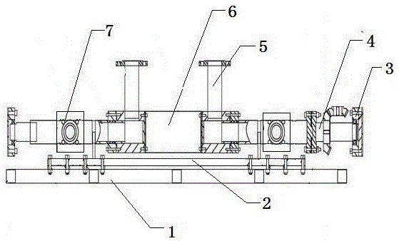
[0013] This embodiment provides a special rotating shaft, which is characterized in that: the special rotating shaft includes installation support (1), conversion frame (2), bearing seat (3), shaft welding parts (4), rotary joint welding piece (5), joint fixing seat (6), liquid medium static interface (7);

[0014] Wherein: the shaft weldment (4) is disconnected from the middle and is connected with the conversion frame (2), the middle is suspended in the air, and a connection port is provided at the upper and lower ends respectively, and the swivel joint weldment (5) is fluid The dynamic and static conversion seal of the medium is mated with one of the connection ports of the shaft weldment (4), the other connection port of the shaft weldment (4) is provided with a bearing seat (3), and the rotary joint weldment (5) is A rotary joint fixing seat (6) is also provided.

[0015] The installation support (1), rotary joint welding piece (5), joint fixing seat (6), bearing seat (3...


PUM


Abstract

The invention provides a special rotating shaft. The special rotating shaft is characterized by comprising a mounting support, a converting frame, a bearing pedestal, a shaft weldment, a rotating joint weldment, a joint fixing seat and a static liquid medium interface, wherein the shaft weldment is broken from the center and is cooperated and connected with the converting frame; the central part of the shaft weldment is suspended, and the upper and lower ends of the shaft weldment are both provided with a connection port; the rotating joint weldment is a fluid medium dynamic-static conversion sealing member and is cooperated and connected with one of the connection ports of the shaft weldment; the other connection port of the shaft weldment is provided with the bearing pedestal; and the rotating joint weldment is provided with the rotating joint fixing seat. The special rotating shaft provided by the invention is simple and reasonable in structure, reliable in performance, high in applicability, good in energy saving effect, long in service life, convenient for maintenance, suitable for mass production and strong in market competitiveness, and can realize flexible rotation and actual mechanical operation.

Description

technical field [0001] The invention relates to the structure of an air-conditioning unit, in particular to a rotating shaft structure for a large air volume air-conditioning unit, and in particular provides a special rotating shaft. Background technique [0002] In the existing large air volume air-conditioning unit structure, no matter whether the air-conditioning unit is in the cooling operation state or the ventilation operation state, the working state of the heat exchanger of the unit is fixed, and the internal resistance of the unit itself cannot vary with the operating state. Self-adjustment and optimization are carried out so that the air-conditioning unit with this structure cannot change the internal resistance to achieve energy-saving effects, and the heat exchange system of the air-conditioning unit with this structure cannot be adjusted with changes in the working environment and working conditions. The location and function are single, and the technology is re...

Claims


Application Information

Patent Timeline
Patent Type & Authority Applications(China)
IPC IPC(8): F16C3/02
Inventor 陈洪厚
Owner 陈洪厚
Learn More