Push-type heating furnace feed mechanism

A push-type heating furnace and feeding mechanism technology, applied in the direction of charge, lighting and heating equipment, furnaces, etc., can solve the problems of damage to the rolling surface of the ingot, inability to ensure the alignment between the center line and the furnace center line, etc. The effect of stability

Active Publication Date: 2017-03-15
艾伯纳工业炉(太仓)有限公司
View PDF4 Cites 3 Cited by
  • Summary
  • Abstract
  • Description
  • Claims
  • Application Information

AI Technical Summary

Problems solved by technology

In the prior art, the roller table in the ingot loading area and the ingot transport area is composed of a row of rollers installed horizontally. In this way, the contact area between the ingot and the roller table is large, and the ingot will inevitably be polluted or damaged during transportation. rolling surface phenomenon
Secondly, the ingot is only aligned with the furnace by the crane. During transportation, it cannot be guaranteed that the centerline of the ingot width is aligned with the centerline of the furnace. Thermal stability throughout the furnace during subsequent heat treatments on the same center line

Method used


Image

  • Push-type heating furnace feed mechanism
  • Push-type heating furnace feed mechanism
  • Push-type heating furnace feed mechanism

Examples


Embodiment Construction

[0025] The technical solutions of the present invention will be further described below in conjunction with the accompanying drawings and specific embodiments.

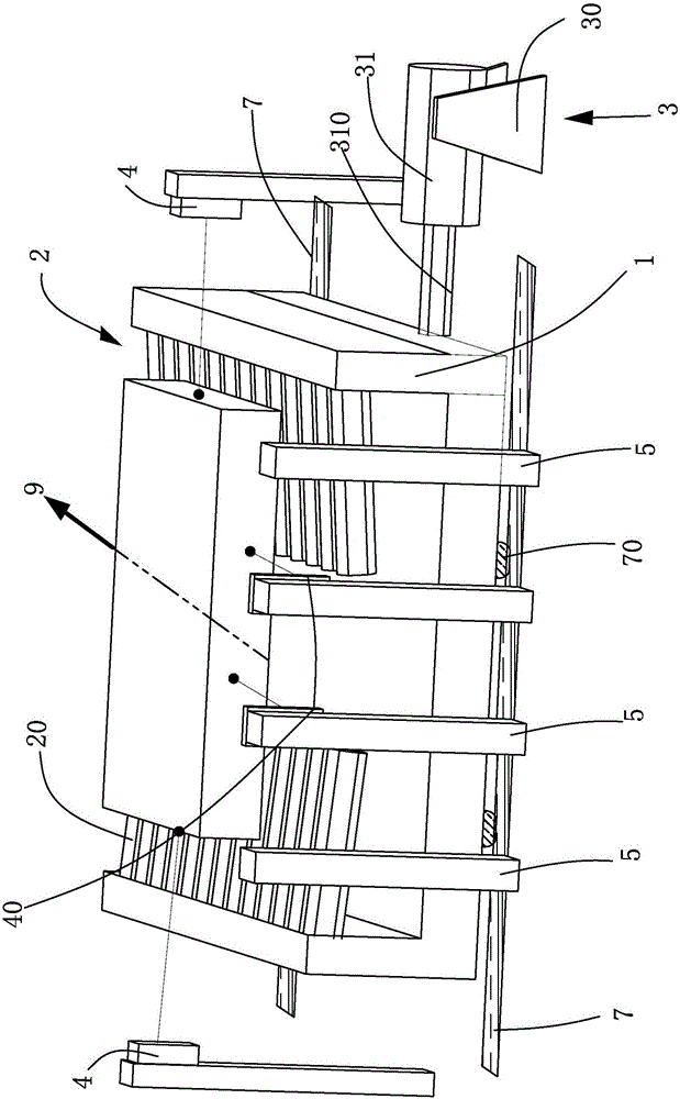
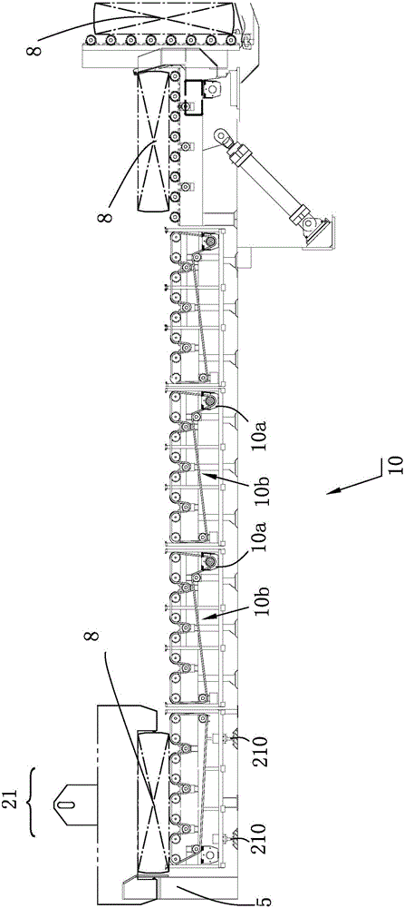
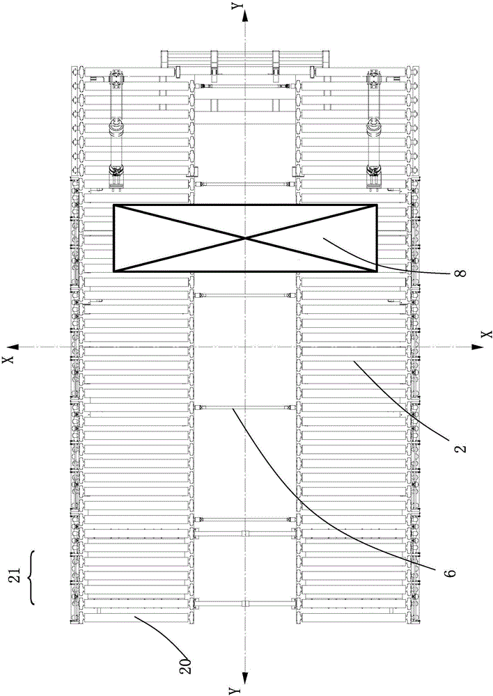
[0026] Such as figure 1 , figure 2 , image 3 As shown, a push-type heating furnace feeding mechanism is used to transport the ingot 8 into the heating furnace. The feeding mechanism has a transverse X and a longitudinal Y perpendicular to each other, and the longitudinal Y is consistent with the conveying direction 9 of the ingot 8. The feeding mechanism includes Frame 1, a roller table 2 for transporting ingots arranged on the frame 1, a first driving device, the frame 1 and the roller table 2 on the frame 1 have two ends in the longitudinal direction Y, and in the transverse direction X There are two sides on the top, and the roller table 2 includes a plurality of rollers 20 that are rotatably arranged on the frame 1 around its own axis driven by the first driving device 10. In particular, the feeding mechanism...


PUM


Abstract

The invention relates to a push-type heating furnace feed mechanism used for conveying ingot castings into a heating furnace. The feed mechanism has a transverse direction and a longitudinal direction which are perpendicular to each other. The longitudinal direction is consistent with the conveying direction of the ingot castings towards the heating furnace. The feed mechanism comprises a rack, a roller table which is arranged on the rack and used for conveying the ingot castings and a first driving device. The rack and the roller table located on the rack are provided with two end portions in the longitudinal direction and are provided with two side portions in the transverse direction. The roller table comprises a plurality of rollers which are driven by the first driving device to rotate around the axes of the rollers to be arranged on the rack. The feed mechanism further comprises sliding wheels arranged on the lower portion of the rack and a second driving device which can drive the rack and the roller table on the rack to make transverse movement. When the feed mechanism disclosed by the invention is used for conveying the ingot castings, the phenomenon that the width center line of the ingot castings aligns the center line of the furnace and the phenomenon that all the ingot castings can be located on the same center line after being transported by a roller way to enter the furnace can be guaranteed, and the heat stability of the inside of the whole furnace in the follow-up heat treatment process is ensured.

Description

technical field [0001] The invention relates to a feeding mechanism of a push type heating furnace. Background technique [0002] The current strong convection propulsion heating furnace equipment is mainly used for reheating and homogenizing aluminum / aluminum alloy ingots. It has the advantages of short heating time, large furnace charging capacity, easy control, and easy to ensure rolling rhythm. It is a high-performance Furnace equipment. The feeding mechanism of the push-type heating furnace includes a fixed frame, a charging roller installed on the frame, and a pushing device. The charging roller is sequentially provided with an ingot loading area, an ingot transport area, and an ingot turning area. The feeding process is generally Loading, conveying, turning the ingot at the entrance, pushing the ingot, and then reaching the furnace. Among them, the roller table of the charging roller accepts the horizontal ingot transported from the ingot fixture on the overhead cra...

Claims


Application Information

Patent Timeline
Patent Type & Authority Applications(China)
IPC IPC(8): F27D3/02F27D19/00
CPCF27D3/028F27D19/00F27D2019/0059F27M2001/1539
Inventor 罗伯特·艾伯纳
Owner 艾伯纳工业炉(太仓)有限公司
Why Eureka
Try Eureka