
Radial multi-channel non-contact slip ring with distributed secondary winding

A secondary winding, multi-channel technology, applied in the direction of transformer/inductor coil/winding/connection, transformer/inductor components, transformers, etc., can solve the problem of increasing axial length and so on

Active Publication Date: 2018-01-30
NANJING UNIV OF AERONAUTICS & ASTRONAUTICS
View PDF6 Cites 0 Cited by
  • Summary
  • Abstract
  • Description
  • Claims
  • Application Information

AI Technical Summary

Problems solved by technology

The diameter of the entire slip ring is equal to that of a single-channel slip ring, but its axial length becomes larger as the number of channels increases

Method used


Image

  • Radial multi-channel non-contact slip ring with distributed secondary winding
  • Radial multi-channel non-contact slip ring with distributed secondary winding
  • Radial multi-channel non-contact slip ring with distributed secondary winding

Examples


Embodiment 1

[0028] The radial three-channel non-contact slip ring with distributed secondary winding of the present invention mainly includes a central shaft, a shielding layer and a three-channel slip ring, and the three-channel slip ring includes a primary side unit and a secondary side unit respectively. In the secondary side unit, 6 turns of winding are placed in the core window of each channel, and 2 turns (or 3 turns) of windings are selected from the core window of each channel to form an output in series, thus forming 3 outputs (or 2 turns) output).

Embodiment 2

[0030] The radial three-channel non-contact slip ring with distributed secondary winding of the present invention mainly includes a central shaft, a shielding layer and a three-channel slip ring, and the three-channel slip ring includes a primary side unit and a secondary side unit respectively. In the secondary side unit, 5 turns of winding are placed in the magnetic core window of each channel, and 1 turn of winding is selected from the magnetic core window of each channel to form one output in series, thus forming 5 outputs.

Embodiment 3

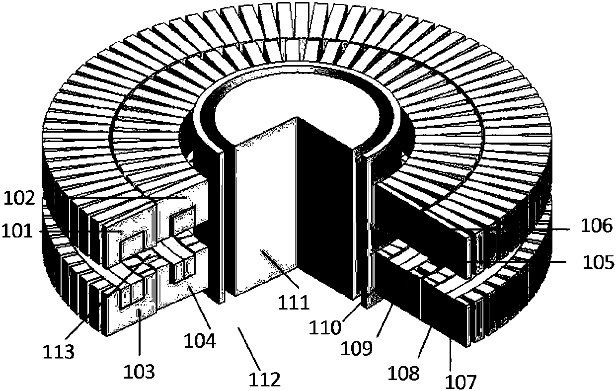
[0032] Such as figure 1 As shown, the primary and secondary side magnetic cores of the radial two-channel non-contact slip ring of the present invention are respectively assembled from separate magnetic cores, and the axial sections of the inner ring channel and the outer ring channel are completely consistent. attached figure 1 Among them, the radial two-channel non-contact slip ring of the present invention includes an inner ring channel and an outer ring channel, and the two inner and outer channels coaxially surround the central axis 111 and the aluminum shielding layer 112 . The radial two-channel non-contact slip ring includes a primary side unit and a secondary side unit, and an air gap 113 is left between the primary side unit and the secondary side unit.

[0033] The primary side unit of the outer ring channel (also called the first channel) includes a primary side magnetic core 101 and a primary side winding 105 wound on the primary side magnetic core; the secondary...


PUM


Abstract

The invention provides a radial multi-channel non-contact slip ring with distributed wound secondary side windings. The radial multi-channel non-contact slip ring mainly comprises a middle shaft, a shielding layer and a multi-channel slip ring, wherein the multi-channel slip ring comprises a primary side unit and a secondary side unit; an air gap is reserved between the primary side unit and the secondary side unit; N turns of windings are put into a magnetic core window of each channel of the secondary side unit and N is an integer greater than or equal to 2; when the secondary side windings are wound, M turns of windings are selected from each channel separately, M is an integer smaller than N and greater than or equal to 1, the M turns of windings are sequentially connected in series from inside to outside to form one path of output, thereby forming multiple paths of distributed wound outputs; when N is an odd number, M is 1, and when N is an even number, M can be an approximate number of N, thereby forming N / M paths of outputs; and the number of outputs can be flexibly adjusted through M. Inductive coupling coefficients of the multiple paths of outputs are basically equal and output characteristics are basically consistent through changing the winding mode of multiple turns of windings at a secondary side of the non-contact slip ring, namely changing concentrated winding into distributed winding. The radial multi-channel non-contact slip ring is suitable for a non-contact power supply occasion with a limited axial space and a relatively large radial space.

Description

technical field [0001] The invention relates to a multi-channel non-contact wireless power supply device, which is suitable for non-contact power transmission in rotating parts, machine joints, speed turntables and other rotating occasions, and belongs to the field of transformers or power conversion. Background technique [0002] Traditional mechanical slip rings are widely used in some special occasions that need to supply power to rotating bodies, such as wind power generation pitch control system, robot joint system, generator excitation system, mine oil field detection system, CT medical system and other occasions. However, due to the inherent mechanical wear of mechanical slip rings, regular maintenance or replacement of brush sets is required, which increases operating costs. In special fields such as aerospace, frequent maintenance and replacement are unrealistic. At the same time, the traditional contact power supply system is prone to contact sparks due to frictio...

Claims


Application Information

Patent Timeline
Patent Type & Authority Patents(China)
IPC IPC(8): H01F27/28H01F38/14
CPCH01F27/2895H01F38/14
Inventor 陈乾宏何广明辛平平陈欣
Owner NANJING UNIV OF AERONAUTICS & ASTRONAUTICS
Learn More