
Crankshaft flange plate steady nail hole machining machine tool

A technology for processing machine tools and nail holes, which is applied to metal processing machinery parts, metal processing equipment, manufacturing tools, etc., can solve problems such as large fluctuations in product quality, high labor intensity for operators, and susceptibility to frozen shoulder, etc., and achieve improvement Processing efficiency and automation level, convenient assembly, simple manufacturing effect

Inactive Publication Date: 2017-03-22
TIANRUN IND TECH CO LTD
View PDF0 Cites 1 Cited by
  • Summary
  • Abstract
  • Description
  • Claims
  • Application Information

AI Technical Summary

Problems solved by technology

[0003] Machining the stable nail hole is an essential and important process in the production process of the crankshaft. In the past, it mainly relied on the Z3040 radial drilling machine to process it manually. The labor intensity of the operator was high, the processing efficiency was low, and the accuracy of the workpiece was poor.
, such as Z3050 radial arm drill operator manual operation consumes a lot of physical strength, is prone to occupational diseases such as frozen shoulder, low processing efficiency, and large fluctuations in product quality.

Method used


Image

  • Crankshaft flange plate steady nail hole machining machine tool

Examples


Embodiment Construction

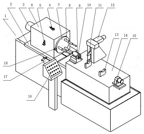
[0013] From figure 1 It can be seen from the figure that a crankshaft flange stable nail hole processing machine tool includes a main bed body 1, a drive motor 3, a rotary power head box 4, a workpiece clamping and fixing device, a PLC control cabinet, a feed cylinder, a rotary Oil cylinder etc. On the left side of the main bed body 1, a sliding guide rail is installed, on which the slide table 2 driven by the feed oil cylinder is installed, and the rotary power head casing 4 is installed on the slide table 2. The workpiece platform 14 is installed on the right side of the main bed body 1, and the workpiece platform 14 is equipped with a workpiece clamping and fixing device. Drive to drive the gear and rack to center the clamping structure to complete the horizontal positioning of the workpiece. Action requirements for automatic clamping and loosening. The workpiece clamping and fixing device includes a headstock pad iron 9, a positioning sleeve 10, a claw 11, a claw clampi...


PUM


Abstract

The invention relates to a crankshaft flange plate steady nail hole machining machine tool. The machine tool comprises a main lathe bed, a drive motor, a rotation power head box body, a workpiece clamping and fixing device and the like; a sliding guide rail is arranged on the left side of the main lathe bed, a sliding table driven by a feeding oil cylinder is arranged on the sliding guide rail, the rotation power head box body is mounted on the sliding table, a rotation power head is mounted in the rotation power head box body, and is a three-station power head driven by a rotation oil cylinder to achieve position changing, a drill bit is mounted on a first station of a cutter disc, a counterboring reamer is mounted on a second station, a precision reaming boring tool is mounted on a third station, and three non-contact induction switches correspond to the three stations; the machine tool is reasonable in structure, convenient to assemble and reliable in work; automatic drilling is carried out firstly, and then is replaced with counterboring for hole reaming, the reamer is used for precise machining, the technology sizes of the position degree, the hole depth, the diameter size and the like of a crankshaft stable nail hole are ensured, and the crankshaft flange plate steady nail hole machining machine tool is an ideal machine tool special for crankshaft flange plate steady nail hole machining.

Description

technical field [0001] The invention relates to a crankshaft processing mechanical device, in particular to a crankshaft flange plate stable nail hole processing machine tool. Background technique [0002] The crankshaft is the heart of the engine, and the bolt hole on the flange is the reference point for machining the crankshaft, which requires very high precision. The process of processed products requires testing the diameter, depth, position, wall thickness, and angle and other parameters. [0003] Machining the stable nail hole is an essential and important process in the production process of the crankshaft. In the past, it mainly relied on the Z3040 radial drilling machine to process it manually. The labor intensity of the operator was high, the processing efficiency was low, and the workpiece accuracy was poor. , For example, Z3050 radial drill operators consume a lot of manual operation, are prone to occupational diseases such as frozen shoulder, low processing ef...

Claims


Application Information

Patent Timeline
Patent Type & Authority Applications(China)
IPC IPC(8): B23P23/02B23Q3/08
CPCB23P23/02B23Q3/062B23Q3/082
Inventor 毕涛程照辉时强
Owner TIANRUN IND TECH CO LTD
Learn More