
Lightweight turnover sleeper

A lightweight, sleeper technology, used in sleeper appliances, railway car body parts, transportation and packaging, etc., can solve the problems of high precision requirements, low anti-vibration performance, and large footprint in the installation process of gas spring brake lines, and achieves flipping. Simple and reliable structure, good dimensional stability, good damping and shock absorption

Active Publication Date: 2017-03-22
CHENGDU TIANZHI LIGHTWEIGHTING TECH CO LTD
View PDF6 Cites 4 Cited by
  • Summary
  • Abstract
  • Description
  • Claims
  • Application Information

AI Technical Summary

Problems solved by technology

[0002] A sleeper is a kind of berth. A sleeper is a berth for passengers to sleep in. When passengers need to rest, the berth needs to be laid flat. Since the existing berth cannot be turned over, when sitting on the lower berth, it is easy to bump into each other when standing up or sitting down. And take up a lot of space
[0003] At present, the sleeping berths of domestic passenger transportation equipment generally use carbon steel, such as Q235 and other materials with high mass density, as the main frame.
[0004] Although the patent document CN101337551A discloses a rail passenger car magnesium alloy sleeper, which uses the rotating shaft on the skeleton to flip the sleeper, and uses the positioning shaft inside the rotating shaft seat to perform positioning, but this method does not fully consider the sleeper in a horizontal state. The shaft has enough strength to bear the weight of passengers on the deck; the installation process requires high precision when using the built-in gas spring brake line, and the subsequent maintenance is complicated

Method used


Image

  • Lightweight turnover sleeper
  • Lightweight turnover sleeper
  • Lightweight turnover sleeper

Examples


Embodiment Construction

[0037] In order to make the object, technical solution and advantages of the present invention clearer, the present invention will be further described in detail below in conjunction with the accompanying drawings.

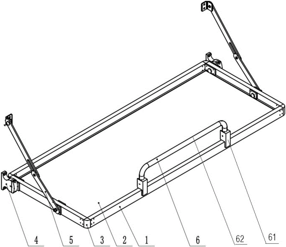
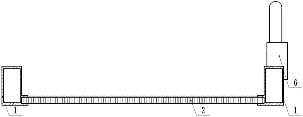
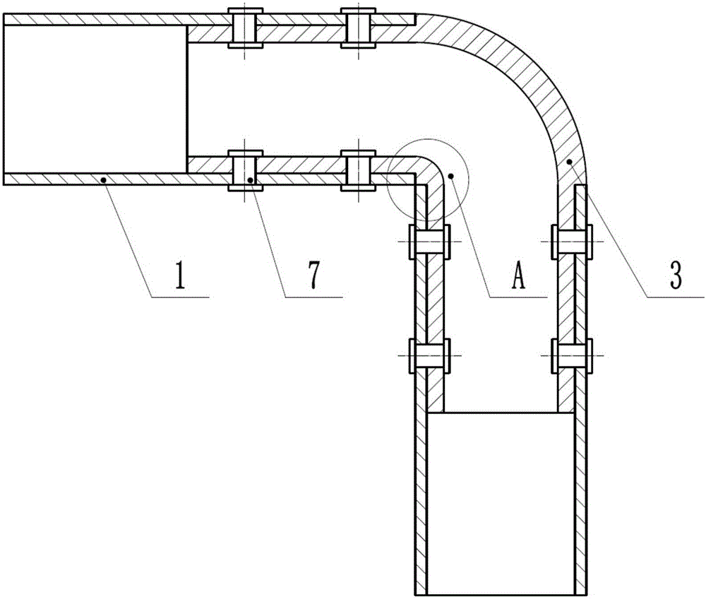
[0038] like figure 1 As shown, the light-weight reversible sleeper disclosed by the present invention includes a bed body, a folding bar 5 and a pendant 4. The bed body includes a sleeper frame and a plank 2 installed on the sleeper frame, and the sleeper frame includes 4 side beams 1, 4 The side beam 1 is connected end to end, and there is a slot on the inner side of the side beam 1 that matches the plank 2, and the plank 2 is installed in the slot; the frame of the sleeper is connected to the side beam 1 in rotation, and one end of the folding rod 5 is connected to the side beam 1 in rotation, and the folding rod The other end of 5 has mounting seat 54, and folding bar 5 is connected with mounting seat 54 in rotation, and the material of paving body, pendant 4 a...


PUM


Abstract

The invention relates to a lightweight turnover sleeper which comprises a sleeper body, folding rods and hanging pieces. The sleeper body comprises a sleeper skeleton and a sleeper plate mounted on the sleeper skeleton. The sleeper skeleton comprises four edge beams which are connected end to end. Slots matched with the sleeper plate are formed in the inner sides of the edge beams. The sleeper plate is mounted in the slots. The sleeper skeleton is rotatably connected with the edge beams. One ends of the folding rods are rotatably connected with the corresponding edge beams, and the other ends of the folding rods are provided with mounting bases. The folding rods are rotatably connected with the mounting bases. The sleeper body, the hanging pieces and the folding rods are made from magnesium alloys. The turnover sleeper is manufactured through lightweight design and is low in density, high in specific strength and specific rigidity, and good in damping shock absorption performance, machining performance and size stability; and the hanging pieces are matched with the folding rods, the bearing strength of the sleeper in a horizontal status is fully considered, the turnover structure is simple and reliable, the flexible and reliable turnover structure can decrease the occupancy rate of the service space, and the lightweight turnover sleeper is suitable for all kinds of complex environments.

Description

technical field [0001] The invention relates to the technical field of transportation equipment, in particular to a lightweight reversible sleeper. Background technique [0002] A sleeper is a kind of berth. A sleeper is a berth for passengers to sleep in. When passengers need to rest, the berth needs to be laid flat. Since the existing berth cannot be turned over, when sitting on the lower berth, it is easy to bump into each other when standing up or sitting down. And it takes up a lot of space. [0003] At present, the sleeping berths of passenger transportation equipment in China generally use carbon steel, such as Q235 and other materials with high mass density, as the main frame. [0004] Although the patent document CN101337551A discloses a rail passenger car magnesium alloy sleeper, which uses the rotating shaft on the skeleton to flip the sleeper, and uses the positioning shaft inside the rotating shaft seat to perform positioning, but this method does not fully con...

Claims


Application Information

Patent Timeline
IPC IPC(8): B61D31/00
CPCB61D31/00
Inventor 郭阳阳周明扬金维栋梁威卢鸿波权高峰
Owner CHENGDU TIANZHI LIGHTWEIGHTING TECH CO LTD
Learn More