
Heating spiral type material conveying device

A conveying device and a spiral technology, which is applied in the field of waste resource disposal equipment, can solve the problems of oil sludge that is difficult to transfer heat and cannot be broken into semi-solid oil sludge, and achieve the effects of improving heat utilization efficiency, uniform heating, and uniform feeding

Active Publication Date: 2017-03-22
浙江博世华环保科技有限公司
View PDF14 Cites 2 Cited by
  • Summary
  • Abstract
  • Description
  • Claims
  • Application Information

AI Technical Summary

Problems solved by technology

However, this technical solution cannot crush the semi-solid sludge, and the annular heating surface between the cylinders can only heat the outer layer of the material, so it is difficult to transfer enough heat to the inside of the sludge to realize the flow of the sludge

Method used


Image

  • Heating spiral type material conveying device
  • Heating spiral type material conveying device
  • Heating spiral type material conveying device

Examples


Embodiment Construction

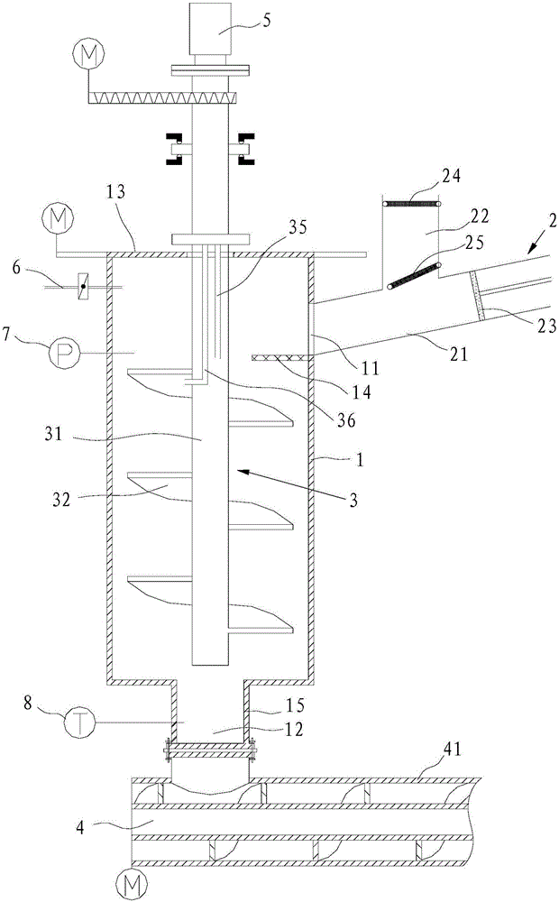
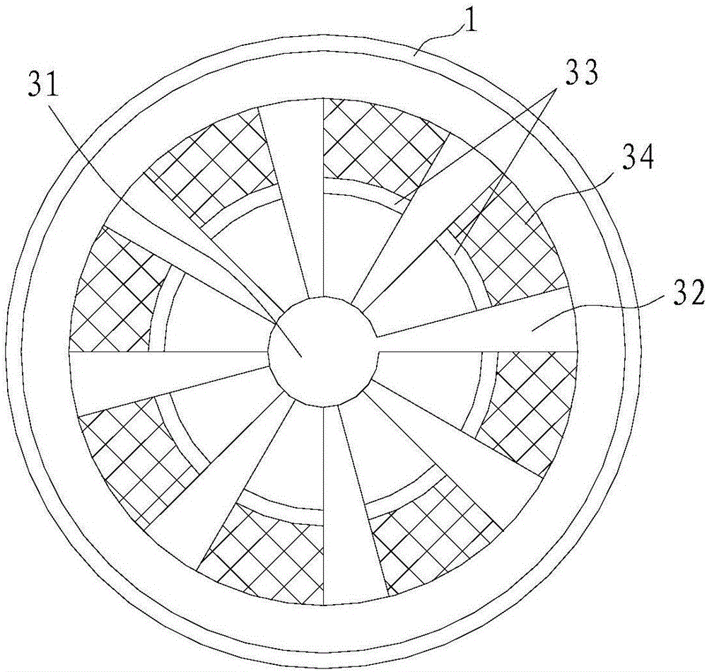
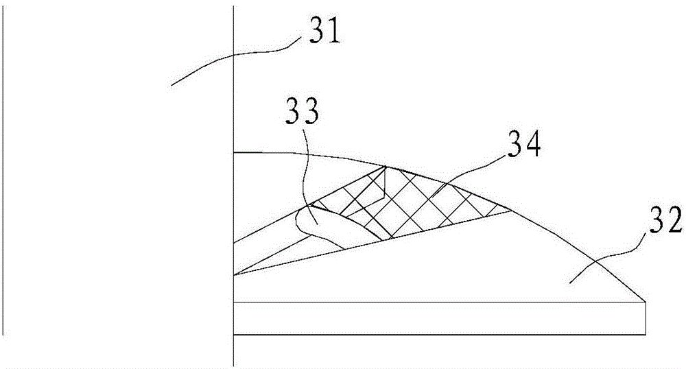
[0028] like Figure 1~4 As shown, a heating screw type material conveying device includes a storage bin housing 1, a feeding mechanism 2, a stirring paddle 3 disposed in the storage bin housing 1, and a horizontally arranged conveying stirring cage 4. The storage bin shell 1 has a material inlet 11 and a material outlet 12 for heating and stirring materials. The top of the storage bin housing 1 is provided with a bin cover 13, and the bin cover 13 is composed of two semicircular covers 131 that can move horizontally. Of course, it can be realized by adding slide rails to the semicircular covers 131, and then driving the opening and closing of the bin cover 13 by a motor. automation. When the stirring paddle 3 is installed, the compartment cover 13 is opened first, and after the stirring paddle 3 is installed, the compartment cover 13 is closed again. The inner wall of the storage bin housing 1 is located below the feed opening 11 and is provided with a feed buffer net 14 . ...


PUM


Abstract

The invention discloses a heating spiral type material conveying device. The heating spiral type material conveying device comprises a warehousing shell, a feeding mechanism, a stirring paddle and a horizontally-arranged conveying stirring cage. The warehousing shell is provided with a feeding port and a discharging port and used for material heating and stirring. The feeding mechanism is connected with the feeding port and used for conveying materials into the warehousing shell. The stirring paddle is arranged in the warehousing shell and comprises a hollow rotating shaft and a plurality of paddle blades spirally arranged on the rotating shaft. The top end of the rotating shaft stretches out of the warehousing shell and is connected with a two-joint rotation connector. The paddle blades are of a hollow structure and sequentially communicate through a connecting pipe. The paddle blades at the topmost part and the bottommost part of the rotating shaft communicate with an air outlet way and an air inlet way of the two-joint rotation connector through a rotating shaft cavity or an air pipe correspondingly. The conveying stirring cage is connected with the discharging port. The heating spiral type material conveying device can effectively crush, stir and heat greasy filth, and smooth heating and conveying of the greasy filth are achieved.

Description

technical field [0001] The invention belongs to the technical field of waste resource disposal equipment, and in particular relates to a heating screw type material conveying device. Background technique [0002] Oil sludge is a solid waste produced in the process of oil extraction, transportation and refining, etc. It contains a large amount of benzene, phenols and volatile toxic and harmful substances, and is included in the "National Hazardous Waste List" for special management. With the expansion of the oil industry, more and more oil sludge is produced, and its unreasonable disposal is increasingly harmful to the environment and human health. On the other hand, the calorific value of oil sludge can reach as high as 4000kcal / kg (on a dry basis), which has considerable energy utilization value. The depletion of non-renewable energy and the environmental damage caused by oil sludge have drawn attention to the harmless and resourceful disposal of oil sludge. Incineration ...

Claims


Application Information

Patent Timeline
Patent Type & Authority Applications(China)
IPC IPC(8): B65G33/24B65G33/14
CPCB65G33/14B65G33/24
Inventor 陈昆柏温俊明戴前进冯猛杨再兴高全喜张明段德超冷玲琴
Owner 浙江博世华环保科技有限公司
Learn More